54
SERVICING
isar - Installation and Servicing
Refer also to Frame 8 - 'Boiler Exploded View'.
IMPORTANT
Before starting the removal procedure, protect the gas and
electrical controls with a waterproof sheet or plastic bag.
1. Refer to Frame 57.
2. Remove the boiler front, bottom and sealing panels.
Refer to Frames 49 & 50.
3. Drain the boiler. Refer to Frame 77.
4. Remove the control box and place on one side. Refer to
Frame 71.
5. Remove the fan / venturi assembly and place on one
side. Refer to Frame 52.
6. Remove the burner and place on one side. Refer to
Frame 53.
7. Remove the ignition and detection electrodes. Refer to
Frames 63 & 64.
8. Remove the spark generator. Refer to Frame 65.
9. Release the flue from the turret. Refer to Frame 26.
10. Remove the turret from the boiler. Refer to Frame 26.
11. Release the silicone tubing from the sampling point.
12. Release the electrical connection to the dry fire
thermistor.
13. Remove the M5 x 10 screw retaining the top flue manifold
casting.
14. Remove the top casting of the flue manifold from the
appliance.
15. Remove the automatic air vent. Refer to Frame 76.
16. Undo the 4 M x 10 screws securing the bottom flue
manifold casting and remove.
81
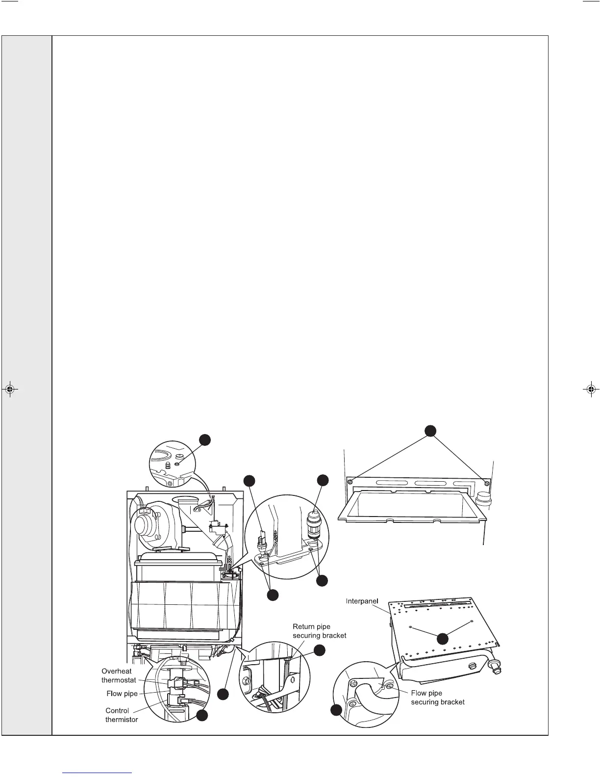
HEAT ENGINE REPLACEMENT
17. Remove the edge clip securing the dry fire thermistor
wiring.
18. Remove the blind grommet to gain access to the return
pipe securing bracket.
19. Remove the M5 screw and remove the return pipe
securing bracket by sliding forwards.
20. Remove the overheat thermostat and the control
thermistor. Refer to Frame 62.
21. Remove the securing pin to release the flow pipe.
22. Remove the condensate ‘S’ trap. Refer to Frame 69.
23. Remove the 2 M5 screws securing the interpanel to the
back panel.
24. Slide the heat exchanger and interpanel assembly upward
to disengage and remove from the casing, complete with
the flow pipe.
25. Remove the 2 M6 countersunk screws, remove the
interpanel and transfer to the new heat exchanger.
26. Remove the M5 screw and remove the flow pipe securing
bracket.
27. Remove the flow pipe and transfer to the new heat
exchanger.
28. Reassemble in reverse order, replacing gaskets or seals
if any sign of damage or deterioration is evident.
Note. The heat exchanger is supplied with new combustion
chamber insulation boards. These should be fitted (refer
to Frame 68 before the burner and fan / venturi
assembly and before the ignition and detection
electrodes are replaced).
29. Refill the boiler. Refer to Frame 36.
30. Check operation of the boiler. Refer to Frame 57.
nm8768
23
13
12
15
16
16
18
20
19
26
25
SERVICING
203319-3.pmd 27/03/2008, 08:1554

 Loading...