8
GFCI Testing
To test the GFCI device, the SureTest
®
creates an imbalance between the hot and neutral con-
ductors by leaking a small amount of current from hot to ground using a fixed value resistor.
The test current applied by the SureTest
®
should not be less than 6mA or greater than 9mA
per UL-1436. A functional GFCI should sense the imbalance and disconnect the power. The
SureTest displays the actual test current in milliamps and trip time in milliseconds.
To conduct a GFCI test, press the GFCI button to enter the GFCI main menu. The GFCI
symbol in the display should be highlighted as the default test. If EPD is lit, then use the
side arrow ( ) to highlight the GFCI symbol. Then, press the GFCI button to activate the
test. The actual current being leaked to ground is displayed. The TEST icon and hourglass
symbol appear on the display to let the user know that the GFCI test is being performed.
The GFCI device should trip within the UL established guideline causing the display to
blank out with the loss of power. When the GFCI device is reset, the unit displays the actual
trip time that the GFCI took to respond to the current imbalance and open the circuit.
Pressing the down arrow button ( ) returns it to the wiring verification mode. If the GFCI
fails to trip, the SureTest terminates the test after 6.5 seconds. Further inspection should
determine whether the GFCI circuitry is faulty, the GFCI is installed incorrectly, or if the cir-
cuit is protected by a GFCI device.
UL Guideline
for trip time:
Notes:
1) In order to test a GFCI in a 2-wire system (no ground), the #61-175 ground continuity
adapter must be used. Connect the alligator clip on the adapter to a ground source,
such as to a metal, water or gas pipe.
2) All appliances or equipment on the ground circuit being tested should be unplugged
to help avoid erroneous readings.
In addition to performing a GFCI test for evaluating personal protection from shock hazards,
the SureTest can also conduct testing to ensure equipment protection from ground faults
exceeding 30mA. The method of operation is the same as the GFCI test noted in the first
paragraph above but uses a different resistor to create a 30mA leakage current from hot-to-
ground. To conduct an EPD test on an Equipment Protective Device, press the GFCI button
to enter the GFCI main menu. The GFCI symbol in the display should be highlighted as the
default test. Press the side arrow ( ) button to highlight the EPD symbol. Then, press
the GFCI button to activate the test. The actual current being leaked to ground is displayed.
The TEST icon and hourglass symbol appear on the display to let the user know that the
EPD test is being performed. The EPD should trip causing the display to blank out with the
Where: T = seconds (s)
I = milliamps (mA)
I
T
=(
20
)
1.43
7
ASCC
1
= Line Voltage (V
HN
)/ (Hot Ω + Neu Ω)
ASCC
2
= Line Voltage (V
HN
)/ (Hot Ω + 1/(1/Neu Ω+ 1/ Grd Ω)
Impedance (Z) Measurements
If the voltage drop measurement exceeds 5%, analyze the hot and neutral impedances. If
one is significantly higher than the other, the problem is with the conductor with the much
higher impedance. Then, check all connections on that conductor back to the panel. If
both impedances appear high, the source can be undersized wire for the length of run, a
bad device, or poor connections at the pigtails, devices, or panel.
The ground impedance measured should be less than 1 ohm as a rule of thumb to ensure
that fault current has a sufficient path back to the panel. IEEE states the ground impedance
should be less than 0.25 ohms to ensure the ground conductor can safely return any fault
current which could damage equipment on the circuit. Surge suppression systems require
a good ground to adequately protect equipment from transient overvoltages. Note that a
small amount of current is applied to the ground conductor to accurately measure its
impedance. By the inherent nature of this test, a GFCI protected circuit will trip unless the
device is temporarily removed from the circuit.
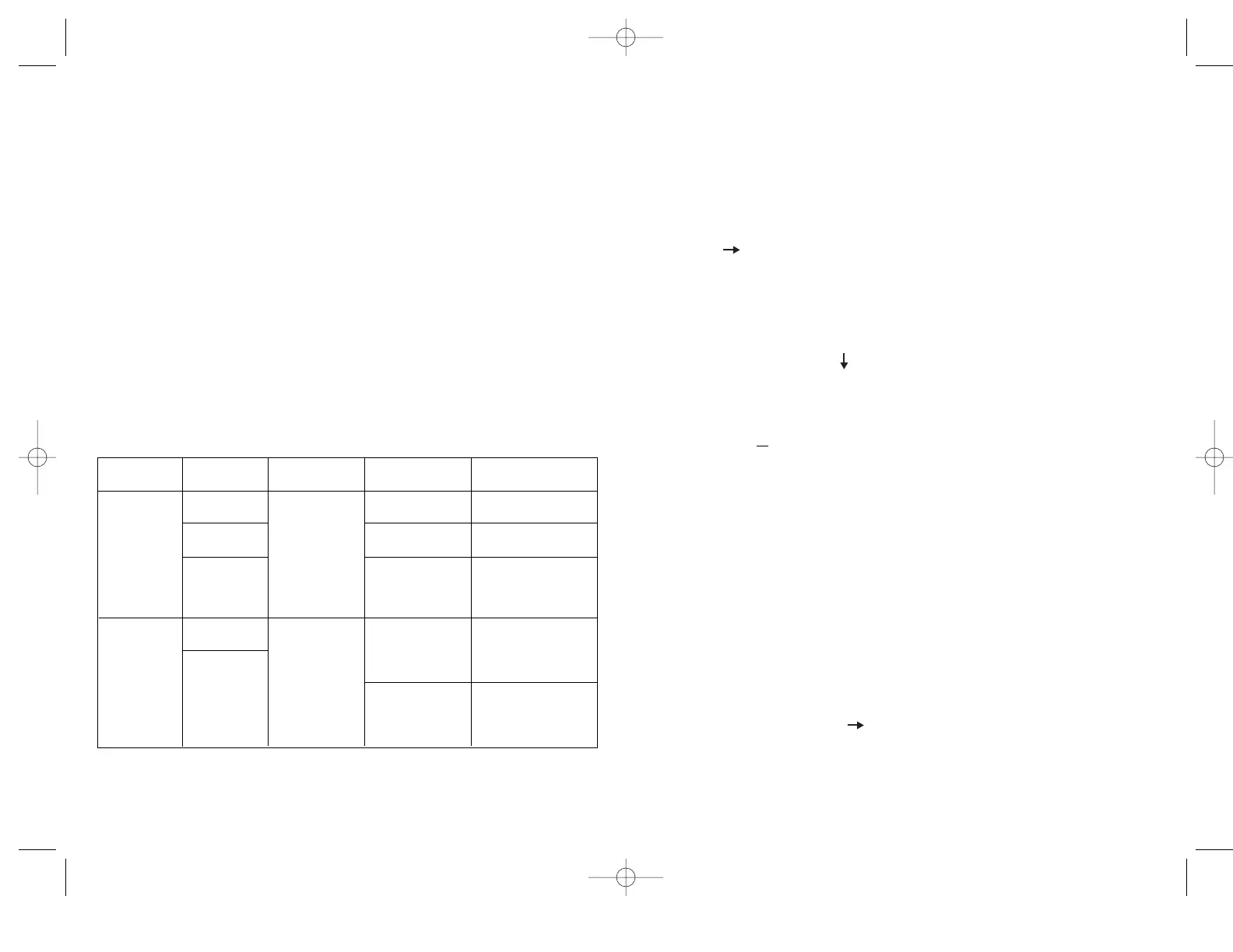
Troubleshooting Tips - Impedances
Measurement Expected Problem Possible Possible
Result Causes Solutions
<0.0048Ω/foot Too much load Redistribute the load
of 14 AWG wire on branch circuit. on the circuit.
<0.003Ω/ foot Undersized wire Check code requirements
of 12 AWG wire for length of run. and rewire if necessary.
<0.001Ω/ foot High resistance Locate high resistance
or 10 AWG wire connection within connection/device
the circuit or at and repair/replace.
the panel.
< 1 Ω to
protect people
High resistance Locate high resistance
connection within connection/device
the circuit or at and repair/replace.
the panel.
Hot and Neutral
Impedance
Ground
Impedance
<0.25Ω to
protect
equipment
Undersized wire
for length of run.
Check code requirements
and re-wire if necessary.
High conductor
impedance
High ground
impedance
 Loading...