Earth Ground
The pathway to ground extends beyond the main panel to the earth ground system. The
earth ground could be a single ground rod, multiple ground rods, a mat or a grid system.
Section 250-56 addresses the system by stating that if the ground electrode is not less
than 25 ohms a second electrode should be added at least 6 feet from the first.
11
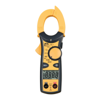
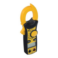
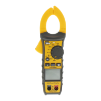
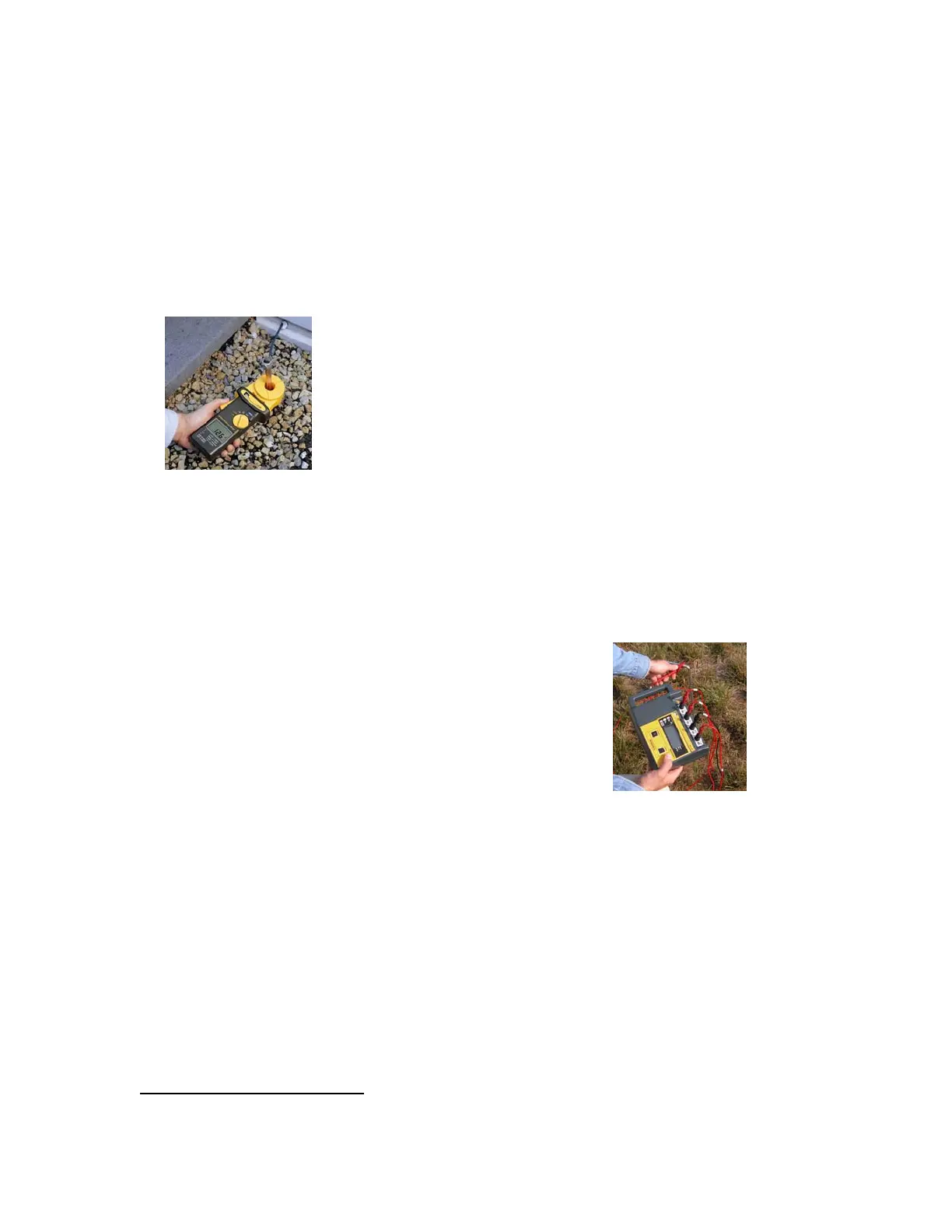
The
grounding system can be tested with a three-pole earth resistance tester, or a ground
resistance clamp meter.
Large ground systems, such as those found in substations and power stations,may
requires a large grounding grid to obtain a sufficiently low value of ground resistance. In
these applications, the soil resistivity can play a large role in determining the
requirements of the grounding grid. Inaccurate resistivity tests can lead to unnecessary
costs in the design of the system. To ensure a low impedance grounding system,
include the ground electrode, or earth ground as part of your standard testing
procedures in your facility.
11
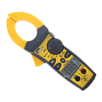
NEC code Article {384-20}
ground resistance clamp meter
enables electricians to measure the
resistance of the ground electrode in a
fraction of the time required using the
traditional three-
oint fall of potential test.
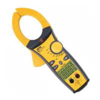
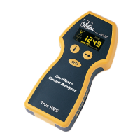
By using a four-pole ground resistance meter,
the soil resistivity can be tested to determine
what the grounding requirements are.
Inaccurate resistivity tests can lead to
unnecessary costs in the design of the
system.
 Loading...