20: PULSE INSTRUCTIONS
20-14 « FC4A MICROSMART USER’S MANUAL »
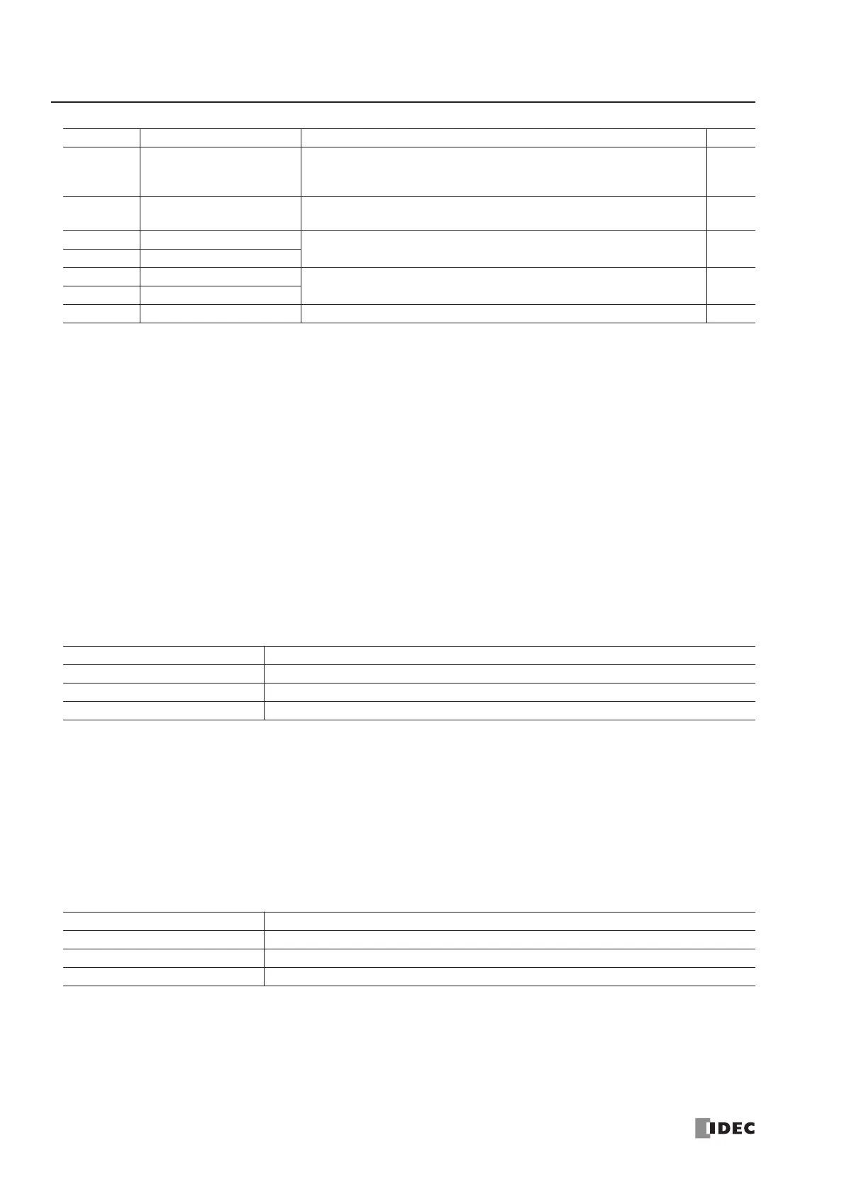
S1+0 Operation Mode
The value stored in the data register designated by operand S1+0 determines the frequency range of the pulse output.
0: 10 to 1,000 Hz
1: 100 to 10,000 Hz
2: 1,000 to 20,000 Hz
3: 10 to 20,000 Hz (upgraded CPU only)
S1+1 Steady Pulse Frequency
When S1+0 is set to 0 through 2, the value stored in the data register designated by operand S1+1 specifies the frequency
of the steady pulse output in percent of the maximum of the frequency range selected by S1+0. When S1+0 is set to 0 (10
to 1,000 Hz) or 1 (100 to 10,000 Hz), valid values for operand S1+1 are 1 through 100, thus the steady pulse frequency can
be 10 to 1,000 Hz or 100 to 10,000 Hz, respectively. When S1+0 is set to 2 (1,000 to 20,000 Hz), valid values for operand
S1+1 are 1 through 20 and the S1+1 value multiplied by 5 determines the steady pulse frequency, thus the steady pulse fre-
quency can be 1,000 to 20,000 Hz.
When S1+0 is set to 3, the value stored in the data register designated by operand S1+1 determines the frequency of the
steady pulse output directly. Valid values are 10 through 20,000.
S1+2 Initial Pulse Frequency
When S1+0 is set to 0 through 2, the value stored in the data register designated by operand S1+2 specifies the frequency
of the initial pulse output in percent of the maximum of the frequency range selected by S1+0. When S1+0 is set to 0 (10
to 1,000 Hz) or 1 (100 to 10,000 Hz), valid values for operand S1+2 are 1 through 100, thus the initial pulse frequency can
be 10 to 1,000 Hz or 100 to 10,000 Hz, respectively. When S1+0 is set to 2 (1,000 to 20,000 Hz), valid values for operand
S1+2 are 1 through 20 and the S1+2 value multiplied by 5 determines the initial pulse frequency, thus the initial pulse fre-
quency can be 1,000 to 20,000 Hz.
When S1+0 is set to 3, the value stored in the data register designated by operand S1+2 determines the frequency of the
initial pulse output directly. Valid values are 10 through 20,000.
S1+4 Reversible control enable
0: Reversible control disabled
1: Reversible control (single-pulse output)
2: Reversible control (dual-pulse output)
R/W
S1+5 Control direction
0: Forward
1: Reverse
R/W
S1+6 Preset value (high word)
1 to 100,000,000 (05F5 E100h) R/W
S1+7 Preset value (low word)
S1+8 Current value (high word)
1 to 100,000,000 (05F5 E100h) R
S1+9 Current value (low word)
S1+10 Error status 0 to 10 R
Operation Mode Steady Pulse Frequency (Hz)
0 or 1 Maximum frequency (Hz) selected by S1+0 × S1+1 value (%)
2 Maximum frequency (Hz) selected by S1+0 × S1+1 value (×5%)
3 Steady pulse frequency (Hz) selected by S1+1
Operation Mode Initial Pulse Frequency (Hz)
0 or 1 Maximum frequency (Hz) selected by S1+0 × S1+2 value (%)
2 Maximum frequency (Hz) selected by S1+0 × S1+2 value (×5%)
3 Initial pulse frequency (Hz) selected by S1+1
Operand Function Description R/W