17: USER COMMUNICATION INSTRUCTIONS
« FC4A MICROSMART USER’S MANUAL » 17-3
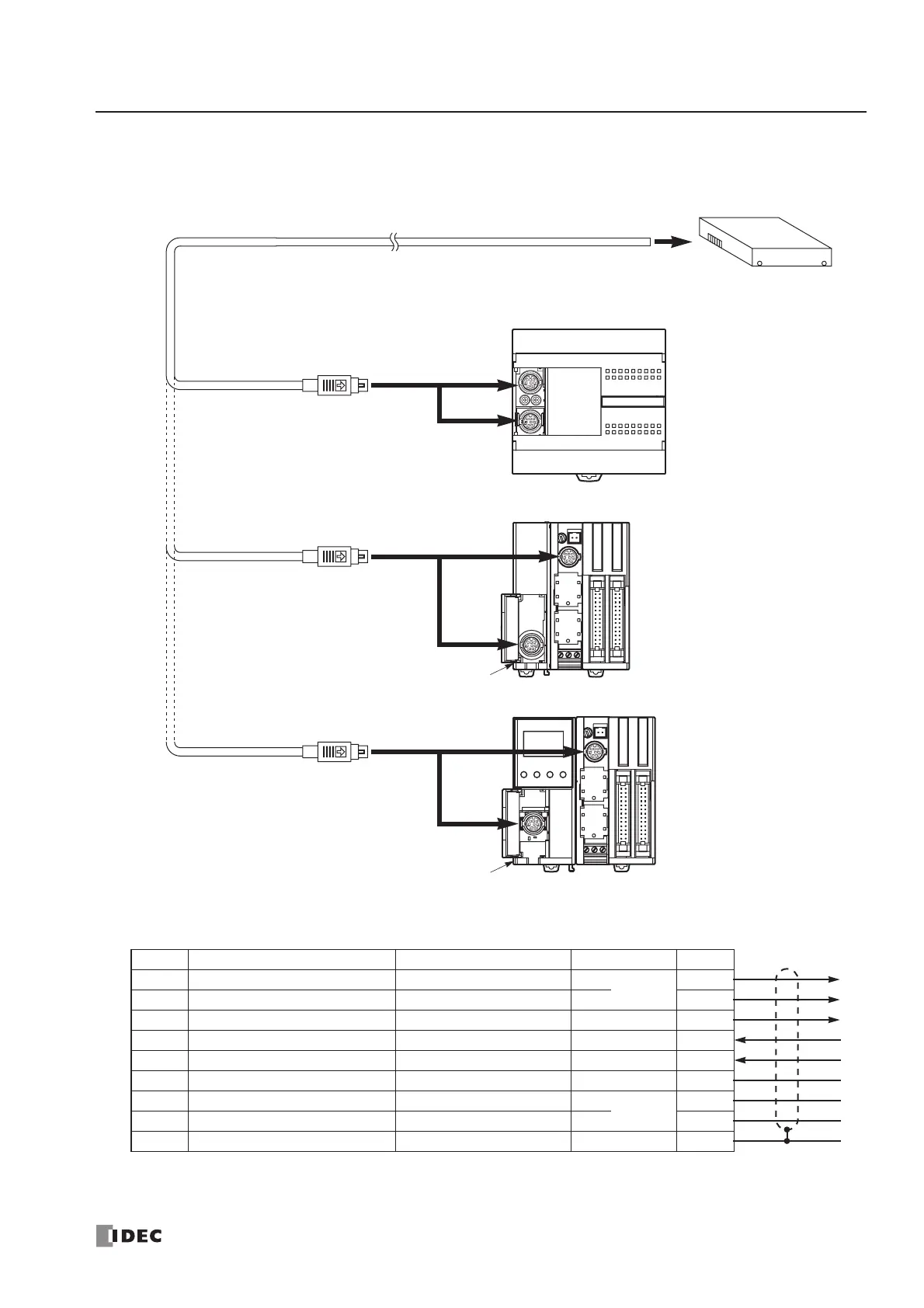
RS232C User Communication System Setup
User Communication Cable 1C
FC2A-KP1C
2.4m (7.87 ft.) long
To RS232C Port
Attach a proper connector to the
open end referring to the cable
connector pinouts shown below.
Cable Connector Pinouts
Note: When preparing a cable for port 1, keep pins 6 and 7 open. If pins 6 and 7 are connected together, user com-
munication cannot be used.
Pin Port 1 Port 2 AWG# Color
1 NC (no connection) RTS (request to send) 28
Twisted
Black
2 NC (no connection) DTR (data terminal ready) 28 Yellow
3 TXD (transmit data) TXD (transmit data) 28 Blue
4 RXD (receive data) RXD (receive data) 28 Green
5 NC (no connection) DSR (data set ready) 28 Brown
6 CMSW (communication switch) SG (signal ground) 28 Gray
7 SG (signal ground) SG (signal ground) 26
Twisted
Red
8 NC (no connection) NC (no connection) 26 White
Cover ———Shield
RS232C Equipment
Signal Direction
To Port 2
RS232C Communication Adapter
FC4A-PC1
To Port 1 (RS232C)
To Port 1 (RS232C)
To Port 2
RS232C Communication Module
FC4A-HPC1
To Port 2
RS232C Communication Adapter
FC4A-PC1
To Port 1 (RS232C)
HMI Base Module
FC4A-HPH1