2: MODULE SPECIFICATIONS
« FC4A MICROSMART USER’S MANUAL » 2-31
Relay Output Module Specifications
Note: When relay output modules are connected to the all-in-one 24-I/O type CPU module or any slim type CPU module, the
maximum number of relay outputs that can be turned on simultaneously, including the outputs on the CPU module, are
shown below.
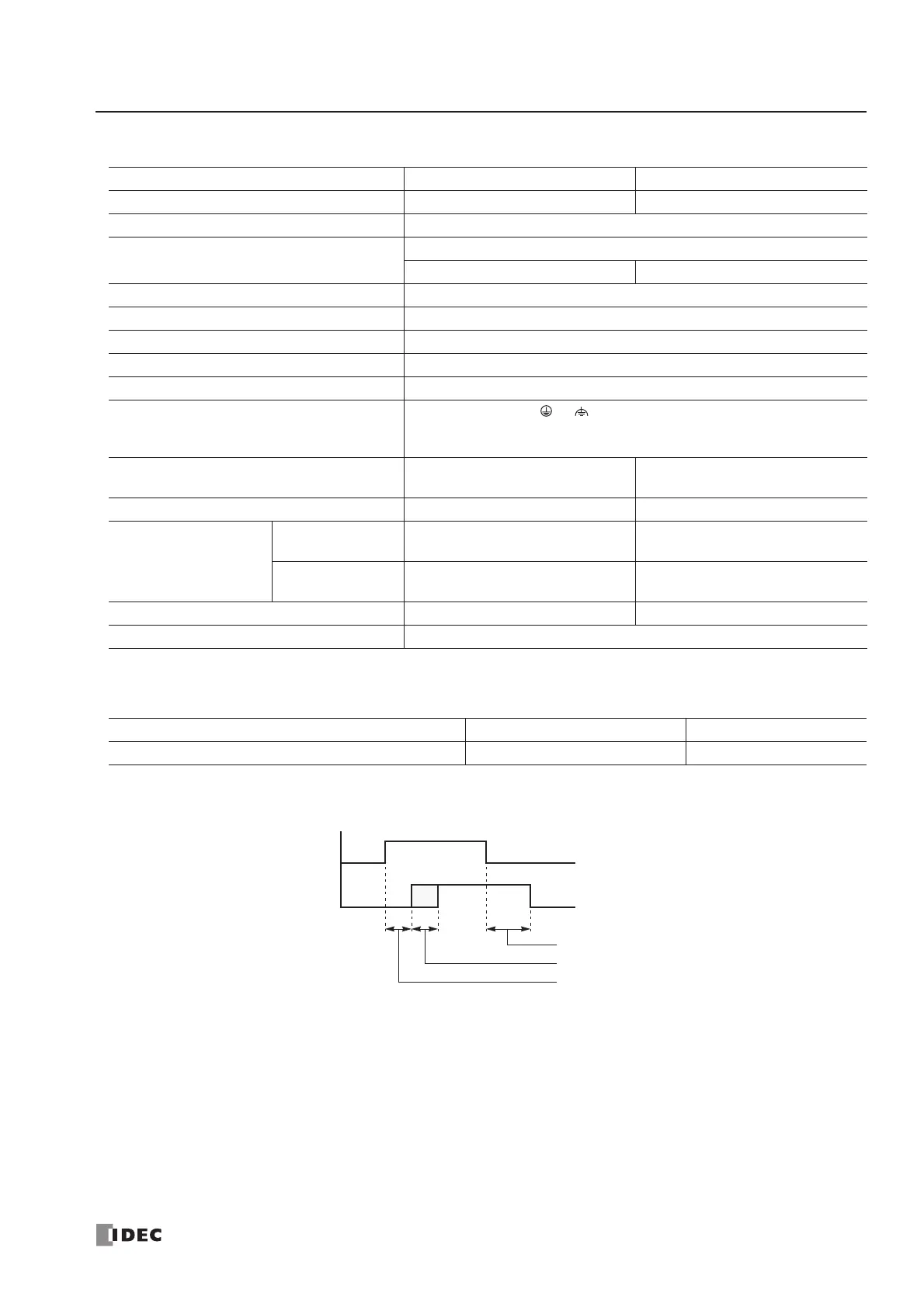
Output Delay
Type No. FC4A-R081 FC4A-R161
Output Points and Common Lines 8 NO contacts in 2 common lines 16 NO contacts in 2 common lines
Terminal Arrangement See Relay Output Module Terminal Arrangement on page 2-32.
Maximum Load Current
2A per point
7A per common line 8A per common line
Minimum Switching Load 0.1 mA/0.1V DC (reference value)
Initial Contact Resistance 30 mΩ maximum
Electrical Life 100,000 operations minimum (rated load 1,800 operations/hour)
Mechanical Life 20,000,000 operations minimum (no load 18,000 operations/hour)
Rated Load (resistive/inductive) 240V AC/2A, 30V DC/2A
Dielectric Strength
Between output and or terminals: 1,500V AC, 1 minute
Between output terminal and internal circuit: 1,500V AC, 1 minute
Between output terminals (COMs): 1,500V AC, 1 minute
Connector on Mother Board
MC1.5/11-G-3.81BK
(Phoenix Contact)
MC1.5/10-G-3.81BK
(Phoenix Contact)
Connector Insertion/Removal Durability 100 times minimum 100 times minimum
Internal Current Draw
All Outputs ON
30 mA (5V DC)
40 mA (24V DC)
45 mA (5V DC)
75 mA (24V DC)
All Outputs OFF
5 mA (5V DC)
0 mA (24V DC)
5 mA (5V DC)
0 mA (24V DC)
Weight 110g 145g
Contact Protection Circuit for Relay Output See page 3-15.
CPU Module Type All-in-One 24-I/O CPU Module Slim Type CPU Module
Maximum Relay Outputs Turning On Simultaneously 33 54