5: SPECIAL FUNCTIONS
« FC4A MICROSMART USER’S MANUAL » 5-13
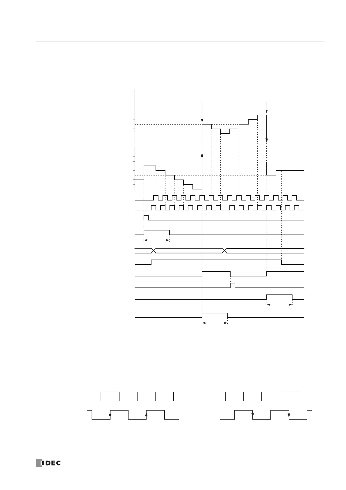
Two-phase High-speed Counter Timing Chart
Example: Reset input I2 is used. Q1 is designated as a comparison output.
Reset Input I2
Reset Value D8046
0
1
2
8
Current Value D8045
1 scan time
The D8046 value at this point becomes the
reset value for the next counting cycle.
Phase A Input I0
Phase B Input I1
655335
Reset Status M8130
3
Gate Input M8031
Comparison Output Q1
Comparison Output Reset M8030
1 scan time
Current Value Overflow M8131
1 scan time
Current Value Underflow M8132
7
6
5
4
3
65532
65533
65534
65535
Underflow Overflow
• When reset input I2 is turned on, the D8046 reset value is set to the D8045 current value, then reset status
M8130 turns on for one scan. If reset input M8032 is turned on, reset status M8130 does not turn on.
• While gate input M8031 is on, the two-phase high-speed counter counts up or down depending on the phase dif-
ference between phase A (input I0) and phase B (input I1).
Phase A
(Input I0)
Phase B
(Input I1)
Count Up (Increment)
Phase A
(Input I0)
Phase B
(Input I1)
Count Down (Decrement)