5: SPECIAL FUNCTIONS
« FC4A MICROSMART USER’S MANUAL » 5-19
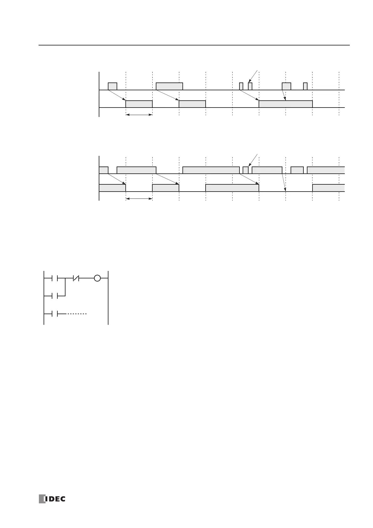
Catching Rising Edge of Input Pulse
Catching Falling Edge of Input Pulse
Note: When two or more pulses enter within one scan, subsequent pulses are ignored.
Example: Maintaining Catch Input
When a catch input is received, the catch input relay assigned to a catch input is turned on for only one scan. This example
demonstrates a program to maintain a catch input status for more than one scan.
Actual Input
ON
OFF
Catch Input Relay
ON
OFF
(M8154-M8157)
Note
END
Processed
1 scan time
(I2 to I5)
Actual Input
ON
OFF
Catch Input Relay
ON
OFF
(M8154-M8157)
Note
END
Processed
(I2 to I5)
1 scan time
M0
M8154
Input I2 is designated as a catch input using the Function Area Settings.
When input I2 is turned on, special internal relay M8154 is turned on, and M0 is maintained
in the self-holding circuit.
When NC input I1 is turned off, the self-holding circuit is unlatched, and M0 is turned off.
M0 is used as an input condition for the subsequent program instructions.
M0
I1 M0