7: BASIC INSTRUCTIONS
« FC4A MICROSMART USER’S MANUAL » 7-9
Timer Accuracy, continued
Timer Counting Error
Every timer instruction operation is individually based on asynchronous 16-bit reference timers. Therefore, an error occurs
depending on the status of the asynchronous 16-bit timer when the timer instruction is executed.
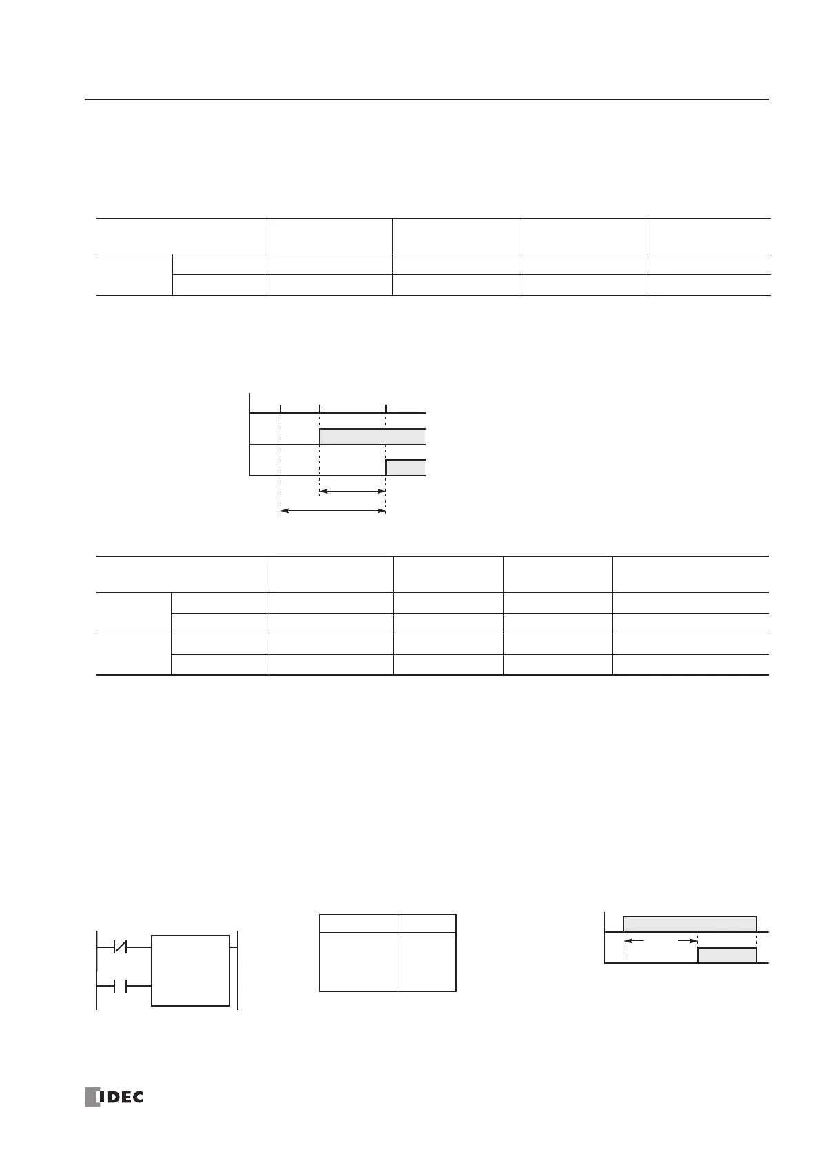
Timeout Output Error
The output RAM status is set to the actual output when the END instruction is processed. So, an error occurs depending on
the timing when the timeout output turns on in a scan cycle. The timeout output error shown below does not include output
delay caused by the hardware.
Maximum and Minimum of Errors
Notes: Advance error does not occur at the timer input and timeout output.
Tet + Tte = 1 scan time
Increment is 1 sec (TML), 100 ms (TIM), 10 ms (TMH), or 1 ms (TMS).
The maximum advance error is: Increment – 1 scan time
The maximum behind error is: 3 scan times
The timer input error and timeout output error shown above do not include the input response time (behind error)
and output response time (behind error) caused by hardware.
Power Failure Memory Protection
Timers TML, TIM, TMH, and TMS do not have power failure protection. A timer with this protection can be devised using
a counter instruction and special internal relay M8121 (1-sec clock), M8122 (100-ms clock), or M8123 (10-ms clock).
Error
TML
(1-sec timer)
TIM
(100-ms timer)
TMH
(10-ms timer)
TMS
(1-ms timer)
Maximum
Advance error 1000 ms 100 ms 10 ms 1 ms
Behind error 1 scan time 1 scan time 1 scan time 1 scan time
Error Timer Input Error
Timer Counting
Error
Timeout Output
Error
Total Error
Minimum
Advance error 0 (Note) 0 0 (Note) 0
Behind error Tet 0 Tte 0
Maximum
Advance error 0 (Note) Increment 0 (Note) Increment – (Tet + Tte)
Behind error 1 scan time + Tet 1 scan time Tte 2 scan times + (Tet + Tte)
be between 0 and one scan time.