17: USER COMMUNICATION INSTRUCTIONS
« FC4A MICROSMART USER’S MANUAL » 17-11
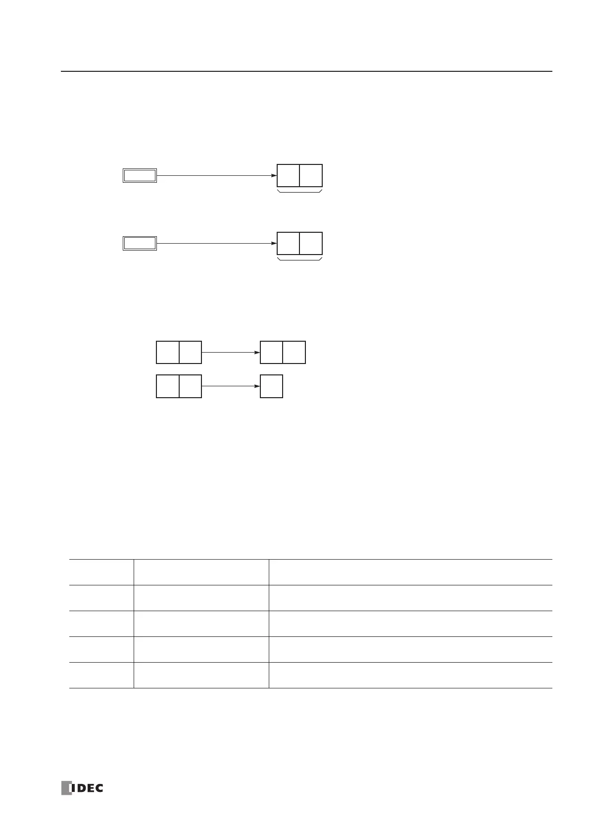
Conversion Type
The BCC calculation result can be converted or not according to the designated conversion type as described below:
Example: BCC calculation result is 0041h.
(1) Binary to ASCII conversion
(2) No conversion
BCC Digits (Bytes)
The quantity of digits (bytes) of the BCC code can be selected from 1 or 2.
Example:
Transmit Completion Output
Designate an output, Q0 through Q107, or an internal relay, M0 through M1277, as an operand for the transmit completion
output. Special internal relays cannot be used.
When the start input for a TXD instruction is turned on, preparation for transmission is initiated, followed by data trans-
mission. When a sequence of all transmission operation is complete, the designated output or internal relay is turned on.
Transmit Status
Designate a data register, D0 through D1298 or D2000 through D7998, as an operand to store the transmit status informa-
tion including a transmission status code and a user communication error code.
Transmit Status Code
If the transmit status code is other than shown above, an error of transmit instruction is suspected. See User Communica-
tion Error Code on page 17-27.
Transmit
Status Code
Status Description
16 Preparing transmission
From turning on the start input for a TXD instruction, until the transmit
data is stored in the internal transmit buffer
32 Transmitting data
From enabling data transmission by an END processing, until all data
transmission is completed
48 Data transmission complete
From completing all data transmission, until the END processing is
completed for the TXD instruction
64 Transmit instruction complete
All transmission operation is completed and the next transmission is
made possible
defaulted to no conversion.
Modbus RTU are defaulted to 2 digits.