EasyManuals Logo

IDEC FC4A-C24R2 User Manual

IDEC FC4A-C24R2
525 pages
To Next Page IconTo Next Page
To Previous Page IconTo Previous Page
Page #30 background imageLoading...
Page #30 background image
2: MODULE SPECIFICATIONS
2-10 « FC4A MICROSMART USERS MANUAL »
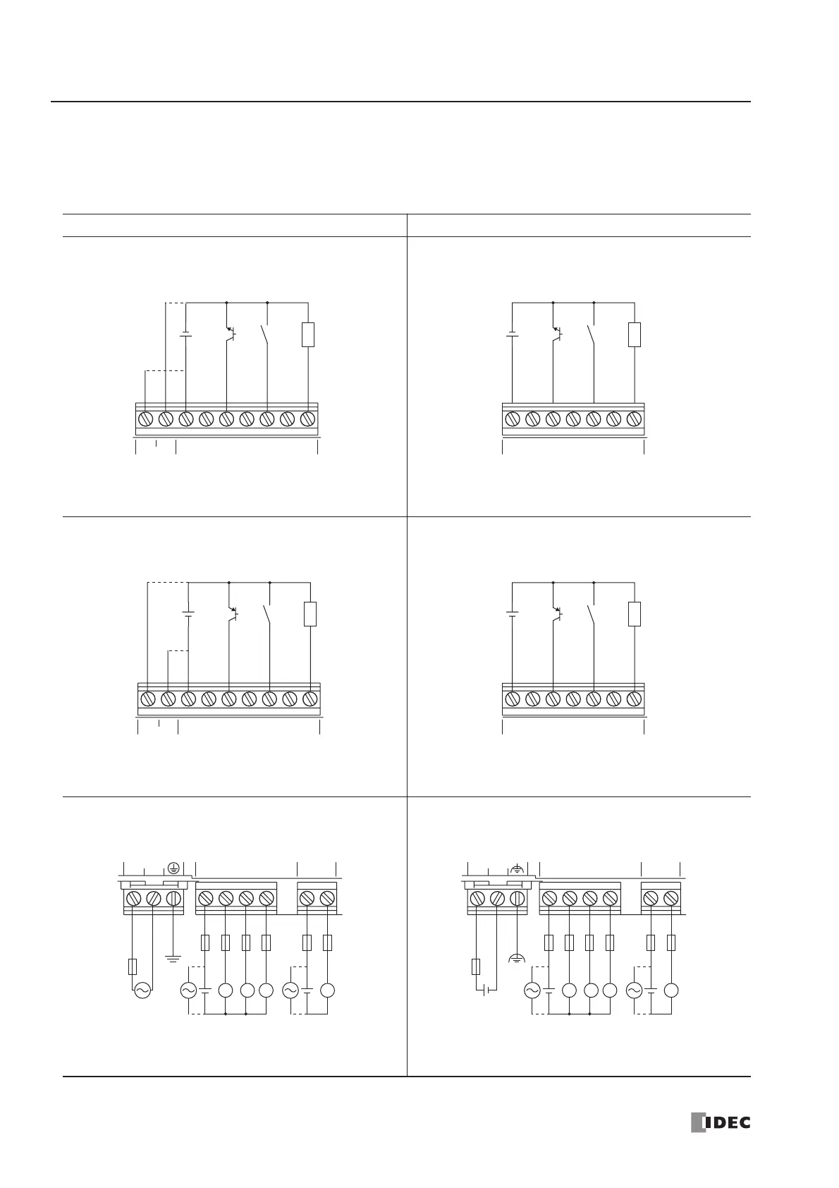
I/O Wiring Diagrams (All-in-One Type CPU Module)
The input and output wiring examples of the CPU modules are shown below. For wiring precautions, see pages 3-13
through 3-16.
AC Power Type CPU Module DC Power Type CPU Module
DC Source Input Wiring DC Source Input Wiring
DC Sink Input Wiring DC Sink Input Wiring
AC Power and Relay Output Wiring DC Power and Relay Output Wiring
+24V 0V
DC OUT COM
DC IN 0 1 2 3 4 5
+
+
Sensor
External
Power
2-wire
Sensor
Power
+
+
External
Power
2-wire
COM
DC IN 0 1 2 3 4 5
Sensor
+24V 0V
DC OUT COM
DC IN 0 1 2 3 4 5
+
+
Sensor
External
Power
2-wire
Sensor
Power
COM
DC IN 0 1 2 3 4 5
+
+
External
Power
2-wire
Sensor
LN
100-240VAC Ry.OUT Ry.OUT
COM0 COM1 30 1 2
+
LLL L
+
L
N
L
N
Fuse
Fuse
Load
Ry.OUT Ry.OUT
COM0 COM1 30 1 2
+–
24VDC
+
LLL L
+
L
N
L
N
Fuse
Fuse
Load
+–

Table of Contents

Questions and Answers:

Question and Answer IconNeed help?

Do you have a question about the IDEC FC4A-C24R2 and is the answer not in the manual?

IDEC FC4A-C24R2 Specifications

General IconGeneral
BrandIDEC
ModelFC4A-C24R2
CategoryController
LanguageEnglish

Related product manuals