20: PULSE INSTRUCTIONS
20-4 « FC4A MICROSMART USER’S MANUAL »
D1+1 Pulse Output Complete
The internal relay designated by operand D1+1 turns on when the PULS1 instruction has completed generating a predeter-
mined number of output pulses or when either PULS instruction is stopped to generate output pulses. When the start input
for the PULS instruction is turned on, the internal relay designated by operand D1+1 turns off.
D1+2 Pulse Output Overflow
The internal relay designated by operand D1+2 turns on when the PULS1 instruction has generated more than the prede-
termined number of output pulses. When the start input for the PULS instruction is turned on, the internal relay designated
by operand D1+2 turns off.
Special Data Register for Pulse Outputs
Upgraded CPU modules have two additional special data registers to store the current frequency of pulse outputs.
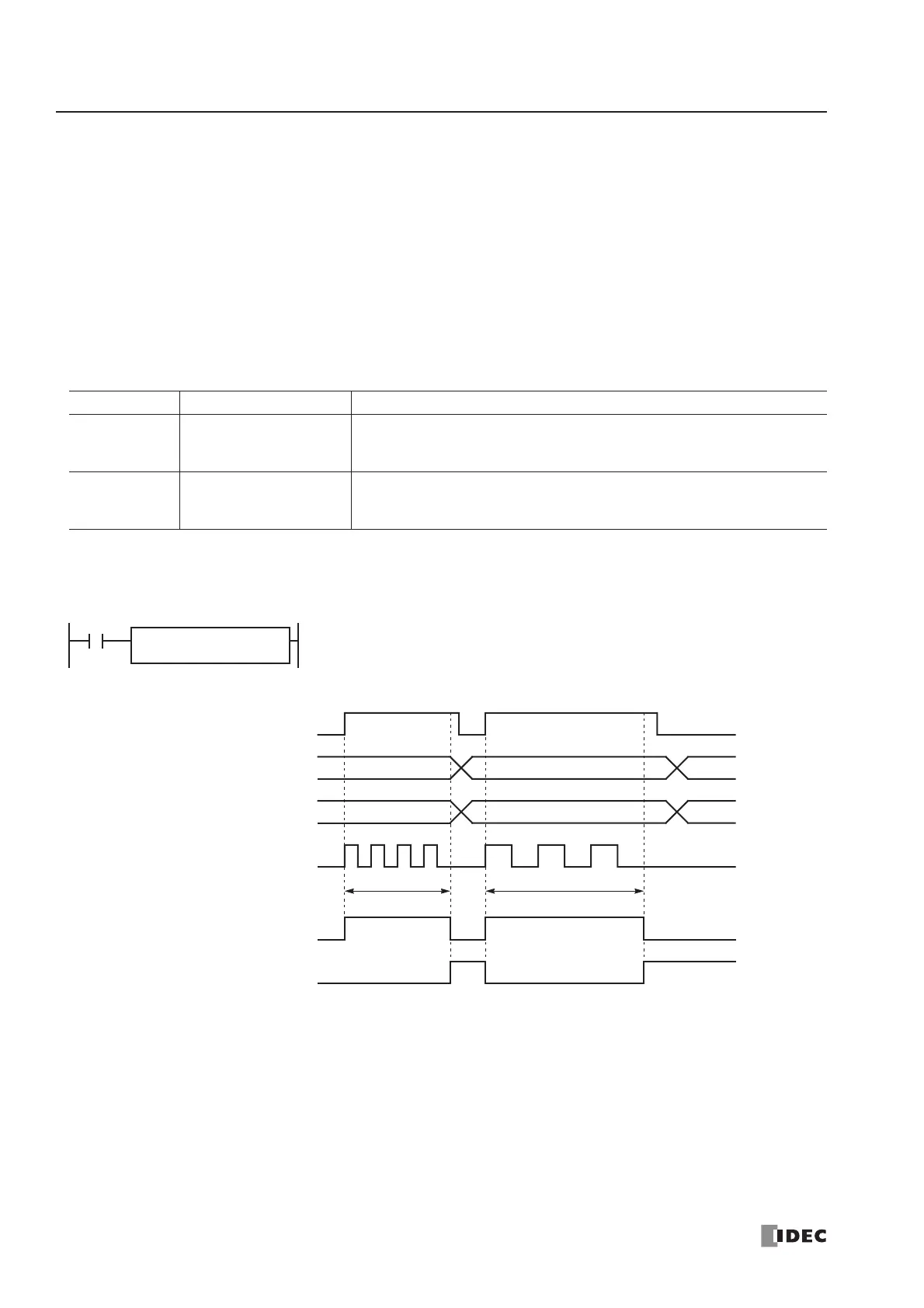
Timing Chart for Enable Pulse Counting
This program demonstrates a timing chart of the PULS1 instruction when pulse counting is enabled.
Allocation No. Function Description
D8055
Current Pulse Frequency
of PULS1 or RAMP (Q0)
While the PULS1 or RAMP instruction is executed, D8055 stores the cur-
rent pulse frequency of output Q0.
The value is updated every scan.
D8056
Current Pulse Frequency
of PULS2 or RAMP (Q1)
While the PULS2 or RAMP (reversible control dual-pulse output) instruction
is executed, D8056 stores the current pulse frequency of output Q1.
The value is updated every scan.
D1
M50
I0
PULS
1
S1
D200
D202 = 1 (enable pulse counting)
Output Pulse Q0
Output Pulse Frequency D201
PV1
FR1
Start Input I0
• When input I0 is turned on, PULS1 starts to generate output pulses at the frequency designated by the value
stored in data register D201. While the output pulses are sent out from output Q0, internal relay M50 remains on.
• When the quantity of generated output pulses reaches the preset value designated by data registers D203 and
D204, PULS1 stops generating output pulses. Then internal relay M50 turns off, and internal relay M51 turns on.
• If the output pulse frequency value in D201 is changed while generating output pulses, the change takes effect in
the next scan. When changing the pulse frequency, make sure that the timing of the change is much slower than
the output pulse frequency, so that the pulse frequency is changed successfully.
• If input I0 is turned off before reaching the preset value, PULS1 stops generating output pulses immediately, then
internal relay M50 turns off and internal relay M51 turns on.