20: PULSE INSTRUCTIONS
20-6 « FC4A MICROSMART USER’S MANUAL »
Sample Program: PULS1
This program demonstrates a user program of the PULS1 instruction to generate 1,000 pulses at a frequency of 3 kHz from
output Q0, followed by 3,000 pulses at a frequency of 5 kHz.
Operand Settings
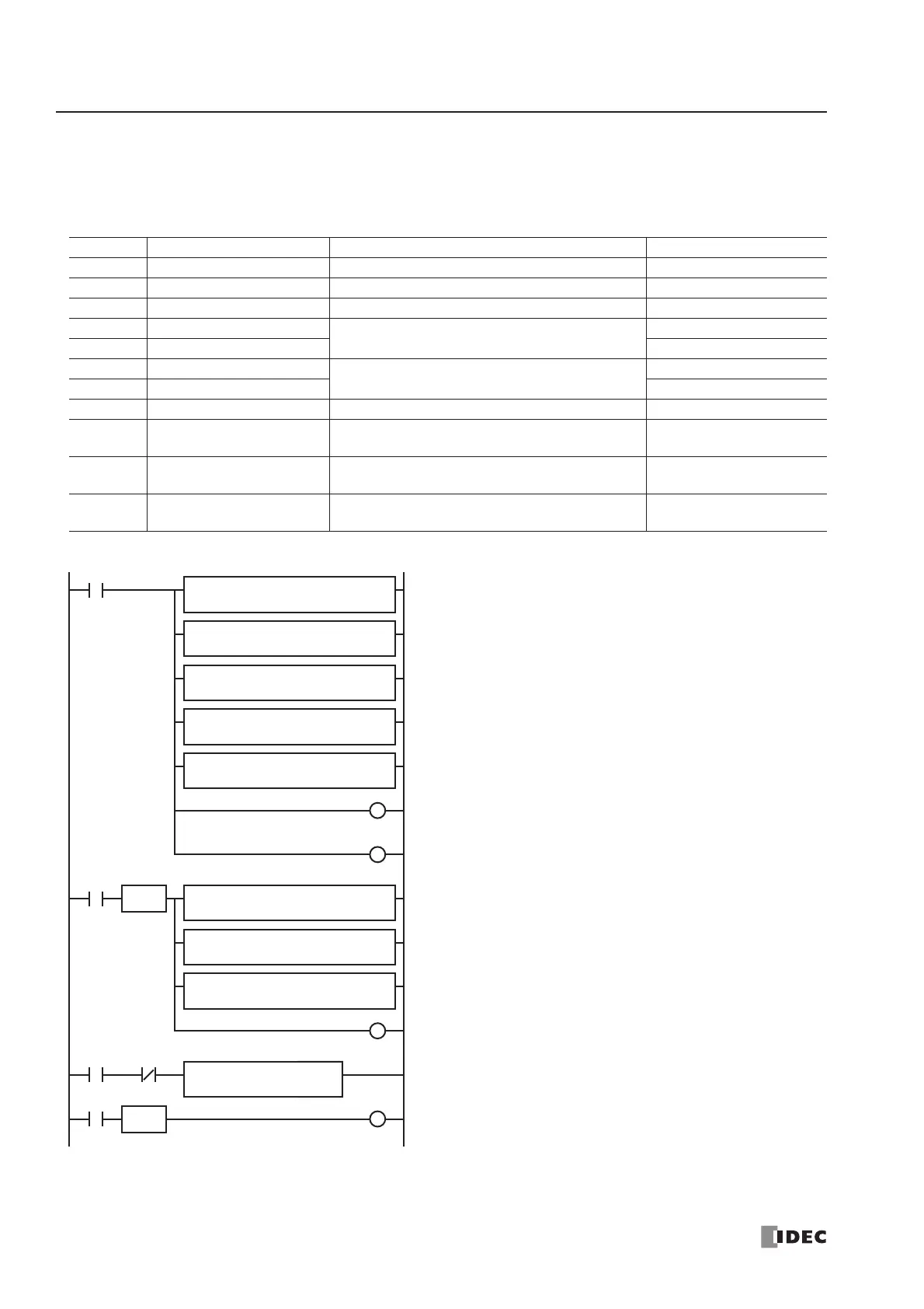
Operand Function Description Allocation No. (Value)
S1+0 Operation mode Frequency range 100 to 10,000 Hz D0 (1)
S1+1 Output pulse frequency 10,000 Hz × 30% (50%) = 3,000 Hz (5,000 Hz) D1 (30) → (50)
S1+2 Pulse counting Enable pulse counting D2 (1)
S1+3 Preset value (high word)
1,000 (3,000)
D3 (0)
S1+4 Preset value (low word) D4 (1000) → (3000)
S1+5 Current value (high word)
0 to 3,000
D5
S1+6 Current value (low word) D6
S1+7 Error status D7
D1+0 Pulse output ON
0: Pulse output OFF
1: Pulse output ON
M100
D1+1 Pulse output complete
0: Pulse output not complete
1: Pulse output complete
M101
D1+2 Pulse output overflow
0: Overflow not occurred
1: Overflow occurred (PULS1 only)
M102
M8120
REPS1 –
50
MOV(W) D1 –
D1
M101
SOTU
M8120 is the initialize pulse special internal relay.
When the CPU starts, five MOV(W) instructions store first-stage
parameters to data registers D0 through D4.
D0 (operation mode): 1 (100 to 10,000 Hz)
D1 (output pulse frequency): 30 (10,000 Hz
× 30% = 3,000 Hz)
D2 (pulse counting): 1 (enable pulse counting)
D3 (preset value high word): 0
D4 (preset value low word): 1,000
Pulse data update flag M1 is reset (pulse data not updated).
Pulse output complete flag M101 is turned off.
When M101 is turned on, three MOV (W) instructions store sec-
ond-stage parameters to data registers D1, D3, and D4.
D1 (output pulse frequency): 50 (10,000 Hz
× 50% = 5,000 Hz)
D3 (preset value high word): 0
D4 (preset value low word): 3,000
Pulse data update flag M1 is set (pulse data updated).
When start input I0 is turned on, PULS1 starts to generate
3,000Hz output pulses in the first stage.
Pulse output complete M101 is turned off.
I0
SOTU
M1
REPS1 –
1
MOV(W) D1 –
D0
REPS1 –
30
MOV(W)
D1 –
D1
REPS1 –
1
MOV(W) D1 –
D2
REPS1 –
0
MOV(W) D1 –
D3
REPS1 –
1000
MOV(W) D1 –
D4
M1
S
M1
R
M101
R
REPS1 –
0
MOV(W) D1 –
D3
REPS1 –
3000
MOV(W) D1 –
D4
M101
R
M101
D1
M100
PULS
1
S1
D0