22: DUAL / TEACHING TIMER INSTRUCTIONS
22-2 « FC4A MICROSMART USER’S MANUAL »
Valid Operands
For the valid operand number range, see page 6-2.
▲ Internal relays M0 through M1277 can be designated as D1. Special internal relays cannot be designated as D1.
Destination operand D2 (system work area) uses 2 data registers starting with the operand designated as D2. Data registers
D0 through D1298 and D2000 through D7998 can be designated as D2. The two data registers are used for a system work
area. Do not use these data registers for destinations of other advanced instructions, and do not change values of these data
registers using the Point Write function on WindLDR. If the data in these data registers are changed, the dual timer does not
operate correctly.
The dual timer instructions cannot be used in an interrupt program. If used, a user program execution error will result,
turning on special internal relay M8004 and the ERR LED on the CPU module.
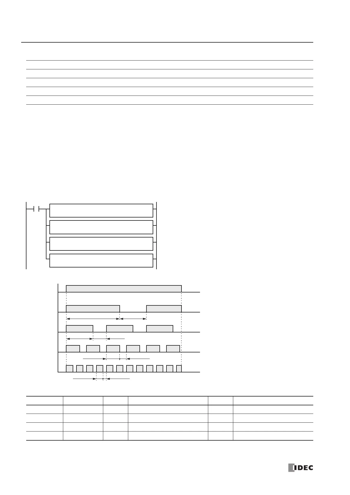
Examples: DTML, DTIM, DTMH, DTMS
For the timer accuracy of timer instructions, see page 7-8.
Operand Function I Q M R T C D Constant
S1 (Source 1) ON duration —————— X 0-65535
S2 (Source 2) OFF duration —————— X 0-65535
D1 (Destination 1) Dual timer output — X ▲ X—— — —
D2 (Destination 2) System work area —————— D0-D7998 —
Instruction Increments S1 ON duration S2 OFF duration
DTML 1 sec 2 1 sec × 2 = 2 sec 1 1 sec × 1 = 1 sec
DTIM 100 ms 10 100 ms × 10 = 1 sec 5 100 ms × 5 = 0.5 sec
DTMH 10 ms 50 10 ms × 50 = 500 ms 25 10 ms × 25 = 250 ms
DTMS 1 ms 250 1 ms × 250 = 250 ms 125 1 ms × 125 = 125 ms