2: MODULE SPECIFICATIONS
2-18 « FC4A MICROSMART USER’S MANUAL »
Relay Output Specifications (Slim Type CPU Module)
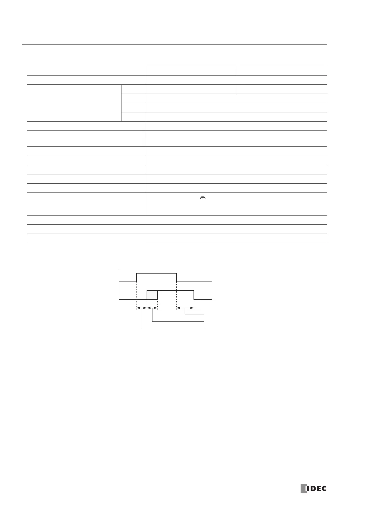
Output Delay
CPU Module FC4A-D20RK1 FC4A-D20RS1
No. of Outputs 8 points including 2 transistor output points
Output Points per Common Line
COM0 (2 points transistor sink output) (2 points transistor source output)
COM1 3 NO contacts
COM2 2 NO contacts
COM3 1 NO contact
Terminal Arrangement See CPU Module Terminal Arrangement on page 2-20.
Maximum Load Current
2A per point
8A per common line
Minimum Switching Load 0.1 mA/0.1V DC (reference value)
Initial Contact Resistance 30 mΩ maximum
Electrical Life 100,000 operations minimum (rated load 1,800 operations/hour)
Mechanical Life 20,000,000 operations minimum (no load 18,000 operations/hour)
Rated Load (resistive/inductive) 240V AC/2A, 30V DC/2A
Dielectric Strength
Between output and terminals: 1,500V AC, 1 minute
Between output terminal and internal circuit: 1,500V AC, 1 minute
Between output terminals (COMs): 1,500V AC, 1 minute
Connector on Mother Board MC1.5/16-G-3.81BK (Phoenix Contact)
Connector Insertion/Removal Durability 100 times minimum
Contact Protection Circuit for Relay Output See page 3-15.