2: MODULE SPECIFICATIONS
2-20 « FC4A MICROSMART USER’S MANUAL »
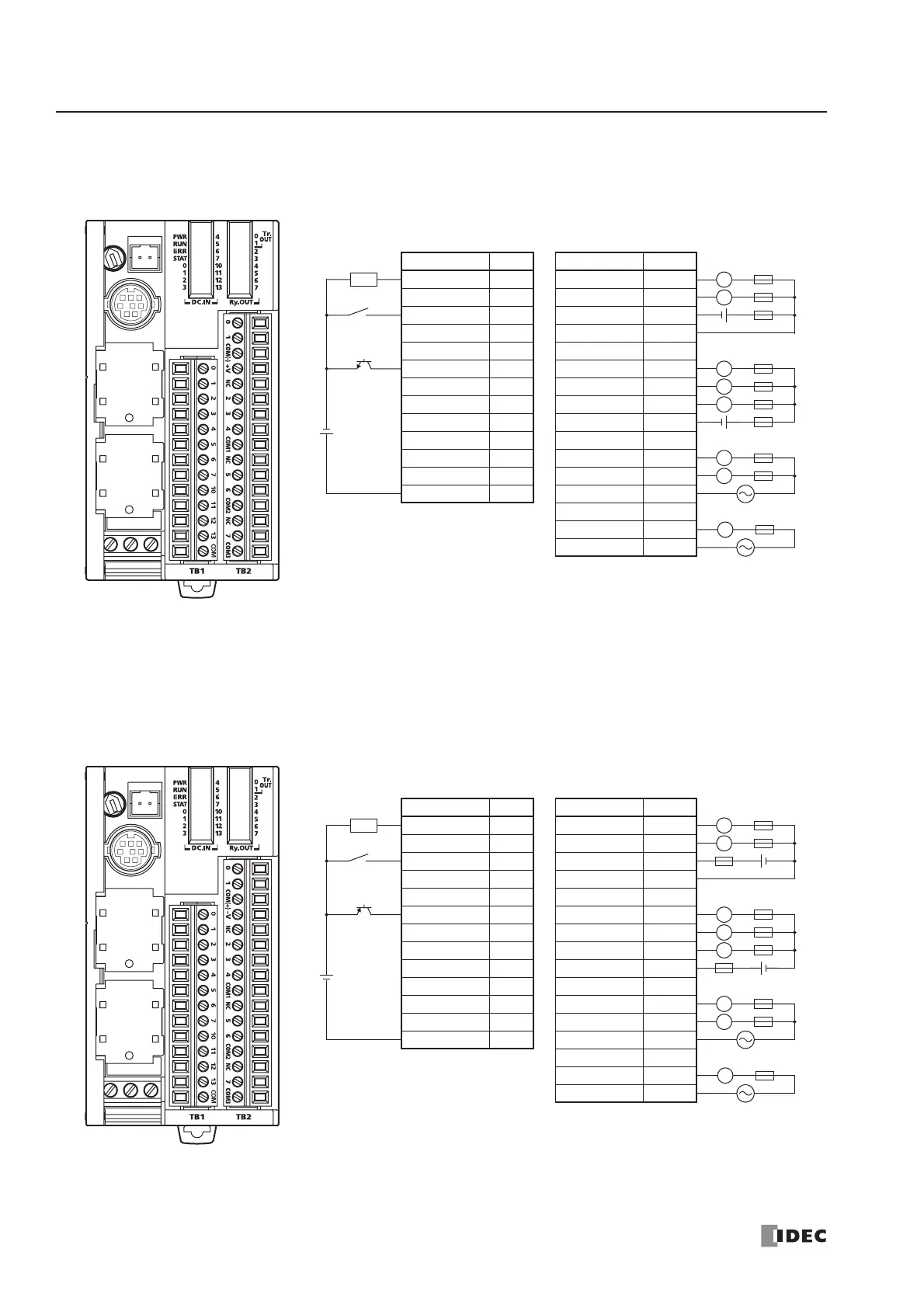
FC4A-D20RK1 (20-I/O Relay and Transistor Sink High-speed Output Type CPU Module)
Applicable Terminal Blocks: TB1 (Left Side) FC4A-PMT13P (supplied with the CPU module)
TB2 (Right Side) FC4A-PMTK16P (supplied with the CPU module)
FC4A-D20RS1 (20-I/O Relay and Transistor Source High-speed Output Type CPU Module)
Applicable Terminal Blocks: TB1 (Left Side) FC4A-PMT13P (supplied with the CPU module)
TB2 (Right Side) FC4A-PMTS16P (supplied with the CPU module)
TB1 TB2
Terminal No. Input Terminal No. Output
1I0 1 Q0
2I1 2 Q1
3I23COM(–)
4I3 4 +V
5I4 5 NC
6I5 6 Q2
7I6 7 Q3
8I7 8 Q4
9 I10 9 COM1
10 I11 10 NC
11 I12 11 Q5
12 I13 12 Q6
13 COM 13 COM2
14 NC
15 Q7
16 COM3
Source Input Wiring
• Outputs Q0 and Q1 are transistor sink outputs; others are relay outputs.
• COM, COM(–), COM1, COM2, and COM3 terminals are not connected
together internally.
• Connect a fuse appropriate for the load.
• For wiring precautions, see pages 3-13 through 3-17.
+
–
+
–
2-wire Sensor
24V DC
NPN
Sink Output Wiring
L
L
L
+–
L
Load
L
Fuse
AC
L
L
L
+–
AC
TB1 TB2
Terminal No. Input Terminal No. Output
1I0 1 Q0
2I1 2 Q1
3I23COM(+)
4I3 4 –V
5I4 5 NC
6I5 6 Q2
7I6 7 Q3
8I7 8 Q4
9 I10 9 COM1
10 I11 10 NC
11 I12 11 Q5
12 I13 12 Q6
13 COM 13 COM2
14 NC
15 Q7
16 COM3
Sink Input Wiring
+
–
+
–
2-wire Sensor
24V DC
PNP
Source Output Wiring
L
L
L
+–
L
Load
L
Fuse
AC
L
L
L
+–
AC
• Outputs Q0 and Q1 are transistor source outputs; others are relay outputs.
• COM, COM(+), COM1, COM2, and COM3 terminals are not connected
together internally.
• Connect a fuse appropriate for the load.
• For wiring precautions, see pages 3-13 through 3-17.