28: AS-INTERFACE MASTER COMMUNICATION
28-36 « FC4A MICROSMART USER’S MANUAL »
HW Series Digital I/O Data Allocation
Input data is sent from slaves to the AS-Interface master. Output data is sent from the AS-Interface master to slaves.
Notes:
SwitchNet HW Series
Slave Unit
Used I/O
Communication
Block Mounting
Position
Input Data
(slave send data)
Output Data
(slave receive data)
DI3 DI2 DI1 DI0 DO3 DO2 DO1 DO0
Pushbutton 1 in ➁ 0X11 1 * ———
Pilot light 1 out ➁ 0011*——X1
Illuminated pushbutton 1 in/1 out ➁ 0X11 1 * ——X1
Selector, Key selector: 2-position 1 in ➁ 0X21 1 * ———
Selector, Key selector: 3-position
1 in ➀ 0X31 1 * ———
1 in ➁ 0X31 1 * ———
Illuminated selector: 2-position 1 in/1 out ➁ 0X21 1 * ——X1
Illuminated selector: 3-position
1 in ➀ 0X31 1 * ———
1 in/1 out ➁ 0X31 1 * ——X1
1. ∗ The AS-Interface master uses bit DO3 for addressing A/B
slaves.
2. In the above table, bits marked with X1, X2, and X3 are used
for SwitchNet I/O data.
3. X1: When pushbutton is pressed, input data is 1 (on). When
not pressed, input data is 0 (off). When output data is 1 (on),
LED is on. When output data is 0 (off), LED is off.
4. X2: The input data from 2-position selector, key selector, and
illuminated selector switches depend on the operator position
as shown below.
5. X3: The input data from 3-position selector, key selector, and
illuminated selector switches depend on the operator position
as shown below.
As shown in the table and figure, 3-position selector, key
selector, and illuminated selector switches use two communi-
cation blocks. Each communication block must have a unique
address, therefore the 3-position selectors require 2 slave
addresses.
6. Unused input bits DI3 and DI2 are 0 (off), and unused input
bits DI1 and DI0 are 1 (on). Slaves ignore unused output data
(—) sent from the master.
2-position Operator
Operator Position Left Right
DI2 0 1
3-position Operator
Operator Position Left Center Right
Communication
Block Mounting
Position
Input Data Bit
➀
DI2 1 0 0
➁ DI2 0 0 1
Selector
Left
Right
Selector
Left
Right
Center
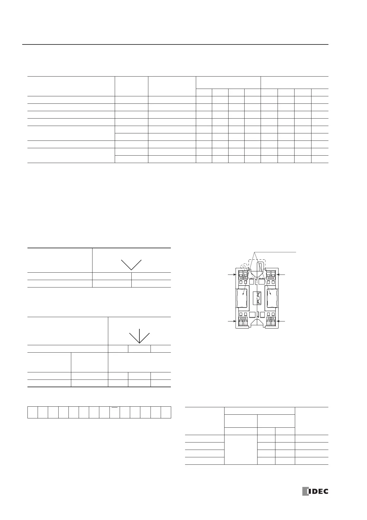
Address Marking Area
Mounting
Position
➀
Mounting
Position
➁
AS-Interface –
AS-Interface +
AS-Interface +
AS-Interface –
Communication Block Mounting Position
(Rear View)
On 3-position selector, key selector, and illuminated
selector switches, communication blocks ➀ and ➁
are mounted in positions shown above.
• Write_Parameter Command • Write_Parameter Settings
00A4A3 A2 A1 A0 1
Sel
P3
P2 P1 P0 PB 1
LED
Brightness
Settings
Remarks
Output
Selection
Control Data
P2 P1 P0
100%
1: DO0
0: DO1
11 Default
50% 0 1
25% 1 0
12.5% 0 0