2: MODULE SPECIFICATIONS
2-44 « FC4A MICROSMART USER’S MANUAL »
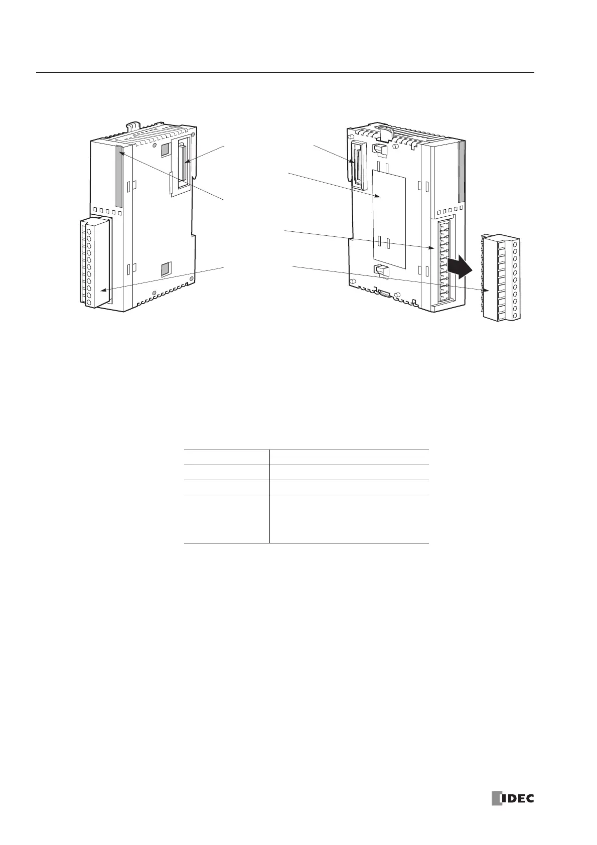
Parts Description
(1) Expansion Connector Connects to the CPU and other I/O modules.
(The all-in-one 10- and 16-I/O type CPU modules cannot be connected.)
(2) Module Label Indicates the analog I/O module Type No. and specifications.
(3) Power LED (PWR) END refresh type FC4A-L03A1, FC4A-L03AP1, FC4A-J2A1, FC4A-K1A1:
Turns on when power is supplied to the analog I/O module.
(3) Status LED (STAT) Ladder refresh type FC4A-J4CN1, FC4A-J8C1, FC4A-J8AT1, FC4A-K2C1:
Indicates the operating status of the analog I/O module.
(4) Terminal No. Indicates terminal numbers.
(5) Cable Terminal All analog I/O modules have a removable terminal block.
Status LED Analog Input Operating Status
OFF Analog I/O module is stopped
ON Normal operation
Flash
Initializing
Changing configuration
Hardware initialization error
External power supply error