2: MODULE SPECIFICATIONS
2-50 « FC4A MICROSMART USER’S MANUAL »
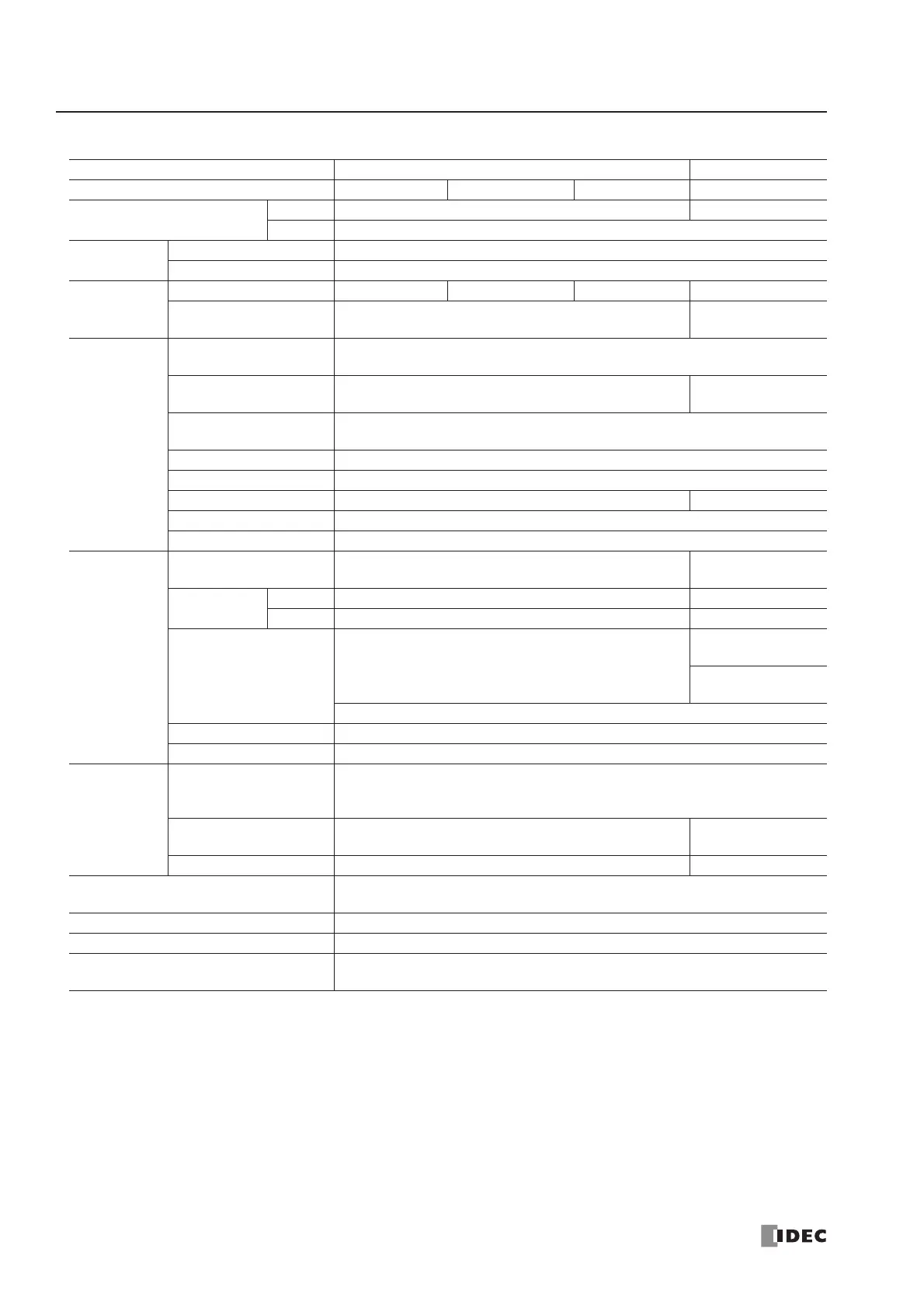
Analog Output Specifications
Note 1: Total input system transfer time = Sample repetition time + Internal processing time
When using the FC4A-J4CN1, FC4A-J8C1, or FC4A-J8AT1, the total input system transfer time increases in proportion to the
number of channels used.
Note 2: The data processed in the analog I/O module can be linear-converted to a value between –32768 and 32767. The
optional range designation, and analog I/O data minimum and maximum values can be selected using data registers allo-
cated to analog I/O modules. See page 26-12.
Note 3: When an error is detected, a corresponding error code is stored to a data register allocated to analog I/O operating
status. See page 26-6.
Category END Refresh Type Ladder Refresh
Type No. FC4A-L03A1 FC4A-L03AP1 FC4A-K1A1 FC4A-K2C1
Output Range
Voltage 0 to 10V DC –10 to +10V DC
Current 4 to 20 mA DC
Load
Load Impedance 2 kΩ minimum (voltage), 300Ω maximum (current)
Applicable Load Type Resistive load
DA
Conversion
Settling Time 50 ms 130 ms 50 ms 1 ms/ch
Total Output System
Transfer Time
Settling time + 1 scan time
1 ms × channels
+ 1 scan time
Output Error
Maximum Error at
25°C
±0.2% of full scale
Temperature
Coefficient
±0.015% of full scale/°C
±0.005% of full
scale/°C
Repeatability after
Stabilization Time
±0.5% of full scale
Output Voltage Drop ±1% of full scale
Non-lineality ±0.2% of full scale
Output Ripple 1 LSB maximum ±0.1% of full scale
Overshoot 0%
Total Error ±1% of full scale
Data
Digital Resolution 4096 increments (12 bits)
50000 increments
(16 bits)
Output Value
of LSB
Voltage 2.5 mV 0.4 mV
Current 4 µA 0.32 µA
Data Type in
Application Program
Default: 0 to 4095 (voltage, current)
–25000 to 25000
(voltage)
0 to 50000
(current)
Optional: –32768 to 32767 (selectable for each channel) (Note 2)
Monotonicity Yes
Current Loop Open Not detectable
Noise
Resistance
Maximum Temporary
Deviation during
Electrical Noise Tests
±3% maximum
(when a 500V clamp voltage is applied to the power supply and I/O lines)
Recommended Cable
for Noise Immunity
Twisted pair shielded cable Twisted pair cable
Crosstalk No crosstalk because of 1 channel output 2 LSB maximum
Isolation
Between input and power circuit: Isolated
Between input and internal circuit: Photocoupler-isolated
Effect of Improper Output Connection No damage
Selection of Analog Output Signal Type Using programming software
Calibration or Verification to Maintain
Rated Accuracy
Not possible