2: MODULE SPECIFICATIONS
« FC4A MICROSMART USER’S MANUAL » 2-53
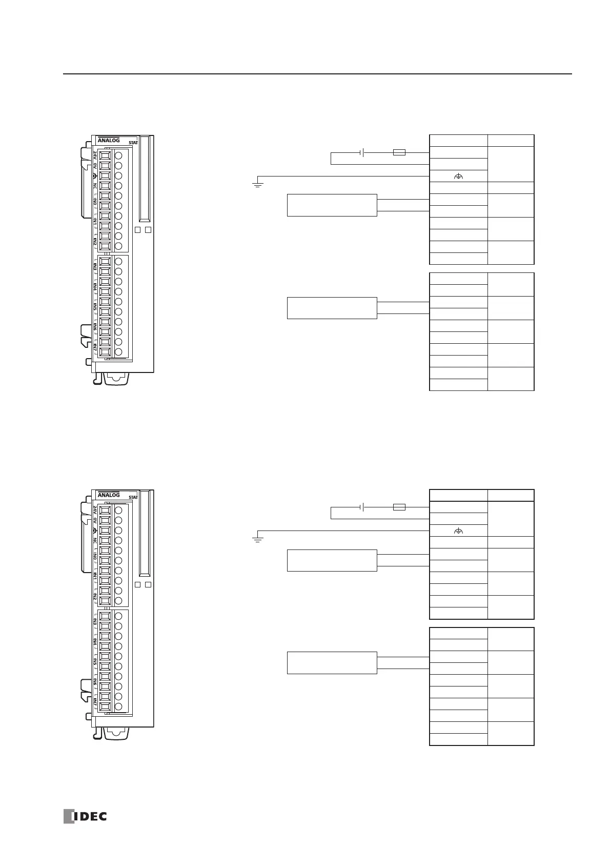
FC4A-J8C1 (Analog Input Module) — Screw Terminal Type
Applicable Terminal Block: FC4A-PMT10P (supplied with the analog input module)
FC4A-J8AT1 (Analog Input Module) — Screw Terminal Type
Applicable Terminal Block: FC4A-PMT10P (supplied with the analog input module)
Terminal No. Channel
24V
24V DC0V
NC —
+
IN0
–
+
IN1
–
+
IN2
–
+
IN3
–
+
IN4
–
+
IN5
–
+
IN6
–
+
IN7
–
Fuse
+–
24V DC
Analog voltage
output device
–
+
Analog current
output device
–
+
• Connect a fuse appropriate for the applied voltage and
current draw, at the position shown in the diagram.
This is required when equipment containing the
MicroSmart is destined for Europe.
• Do not connect any wiring to unused terminals.
• – terminals of input channels IN0 through IN7 are
interconnected.
Terminal No. Channel
24V
24V DC0V
NC —
A
IN0
B
A
IN1
B
A
IN2
B
A
IN3
B
A
IN4
B
A
IN5
B
A
IN6
B
A
IN7
B
Fuse
+–
24V DC
NTC
Thermistor
B
A
PTC
Thermistor
B
A
• Connect a fuse appropriate for the applied voltage and
current draw, at the position shown in the diagram.
This is required when equipment containing the
MicroSmart is destined for Europe.
• Do not connect any wiring to unused terminals.