2: MODULE SPECIFICATIONS
2-56 « FC4A MICROSMART USER’S MANUAL »
Power Supply for Analog I/O Modules
When supplying power to the analog I/O modules, take the following considerations.
•
Power Supply for FC4A-L03A1, FC4A-L03AP1, FC4A-J2A1, and FC4A-K1A1
Use separate power supplies for the MicroSmart CPU module and FC4A-L03A1, FC4A-L03AP1, FC4A-J2A1, and FC4A-
K1A1
. Power up the analog I/O modules at least 1 second earlier than the CPU module. This is recommended to ensure
correct operation of the analog I/O control.
Note: When re-powering up the analog I/O modules FC4A-L03A1, -L03AP1, and -J2A1, a time interval is needed before turn-
ing on these modules. If a single power supply is used for the MicroSmart CPU module and the analog I/O modules, turn on
the analog I/O modules at least 5 seconds (at 25°C) after turning off these modules. If separate power supplies are used
for the MicroSmart CPU module and the analog I/O modules, turn on the analog I/O modules at least 30 seconds (at 25°C)
after turning off the analog I/O modules whether the CPU module is powered up or not.
• Power Supply for FC4A-J4CN1, FC4A-J8C1, FC4A-J8AT1, and FC4A-K2C1
Use the same power supply for the MicroSmart CPU module and FC4A-J4CN1, FC4A-J8C1, FC4A-J8AT1, and FC4A-K2C1
to suppress the influence of noises.
After the CPU module has started to run, ladder refresh type analog input modules perform initialization for a maximum
of 5 seconds. During this period, the analog input data have an indefinite value. Design the user program to make sure that
the analog input data are read to the CPU module after the analog input operating status has changed to 0 (normal opera-
tion). For the analog input operating status, see page 26-13.
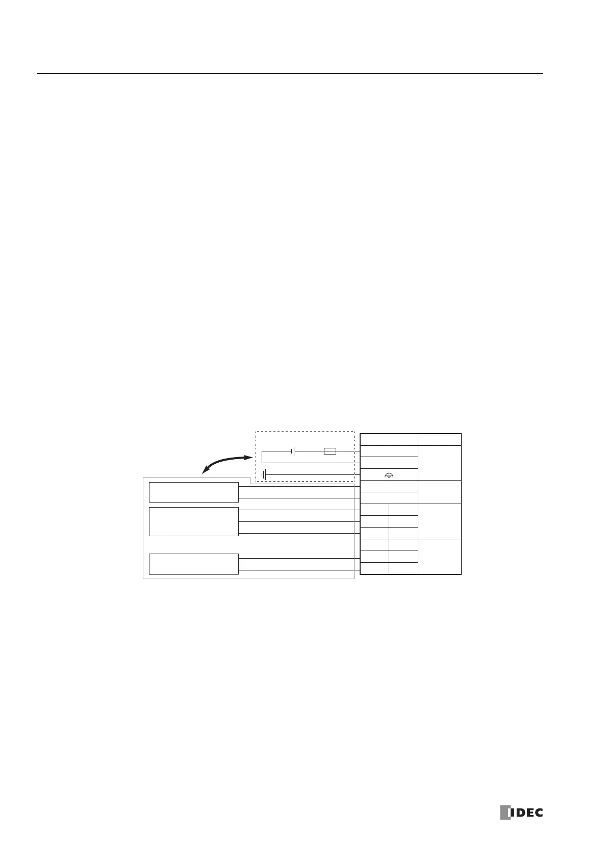
Wiring Analog I/O Lines
Separate the analog I/O lines, particularly resistance thermometer inputs, from motor lines as much as possible to suppress
the influence of noises.
from the power line.