19
HS5L Interlock Switches with Solenoid
Safety Precautions
• In order to avoid electric shock or re, turn power off before
installation, removal, wiring, maintenance, or inspection of the
interlock switch.
• If relays are used in the circuit between the interlock switch
and the load, use only safety relays, since welded or sticking
contacts of standard relays may invalidate the functions of the
interlock switch. Perform a risk assessment and make a safety
circuit which satises the requirements of the safety category.
• Do not place a PLC in the circuit between the interlock switch
and the load. Safety security can be endangered in the event of
a malfunction of the PLC.
• Do not disassemble or modify the interlock switch, otherwise a
malfunction or an accident may occur.
• Do not install the actuator in a location where a human body may
come into contact. Otherwise injury may occur.
• Solenoid lock is locked when energized, and unlocked when
de-energized. When energization is interrupted due to wire
disconnection or other failures, the interlock switch may be
unlocked causing possible danger to the operators. Solenoid
lock must not be used in applications where locking is strictly
required for safety. Perform a risk assessment and determine
whether solenoid lock is appropriate.
• When changing the head orientation, disconnect the cable and
turn the manual unlock to the UNLOCK position in advance. If
the head orientation is changed when the cable is connected
and the manual unlock is in the LOCK position, machines may
start to operate, causing danger to the operators.
• HS5L interlock switches are Type 2 low level coded
interlocking devices (ISO14119). According to ISO14119, the
following is required to minimize defeat when installing and
constructing systems:
1. Prevent dismantling or de-positioning of the elements of
the interlocking device by use of non-detachable xing (e.g.
welding, gluing, one-way screws, riveting). However, use of
non-detachable xing can be an inappropriate solution in
cases where a failure of the interlocking device during lifetime
of the machinery can be expected and a fast change is
necessary. In this case measures mentioned below, should be
used to provide the required level of risk reduction.
2. Apply at least one out of the four measures below.
➀ Mounting out of reach.
➁ Physical obstruction or shielding.
➂ Mounting in hidden position.
➃ Integration of defeat monitoring by means of status
monitoring/cyclic testing.
• Do not use the interlock switch as a door stop. Install a
mechanical door stop at the end of the door to protect the
interlock switch against excessive force.
• Do not apply excessive shock to the interlock switch when
opening or closing the door. A shock to the interlock switch
exceeding 1,000m/s
2
may cause damage to the interlock
switch.
• Prevent foreign objects such as dust and liquids from
entering the interlock switch while connecting a conduit or
wiring.
• Plug the unused actuator entry slot using the slot plug
supplied with the interlock switch.
• Do not store the interlock switches in a dusty, humid, or
organic-gas atmosphere, or in an area subjected to direct
sunlight.
• Use proprietary actuators only. When other actuators are
used, the interlock switch may be damaged.
• The locking strength is rated at 1400N. Do not apply a load
higher than the rated value. When a higher load is expected,
provide an additional system consisting of another interlock
switch without lock (such as the HS5D interlock switch) or a
sensor to detect door opening and stop the machine.
• Regardless of door types, do not use the interlock switch
as a door lock. Install a separate lock using a latch or other
measures.
• While the solenoid is energized, the switch temperature
rises approximately 40°C above the ambient temperature (to
approximately 95°C while the ambient temperature is 55°C).
Do not touch to prevent burns. If cables come into contact
with the switch, use heat-resistant cables.
• Although the HS9Z-A51A/A52A actuators alleviate shock
when the actuator enters a slot in the interlock switch, make
sure that excessive shock is not applied. If the Rubber
Bushings become deformed or cracked, replace with new
ones.
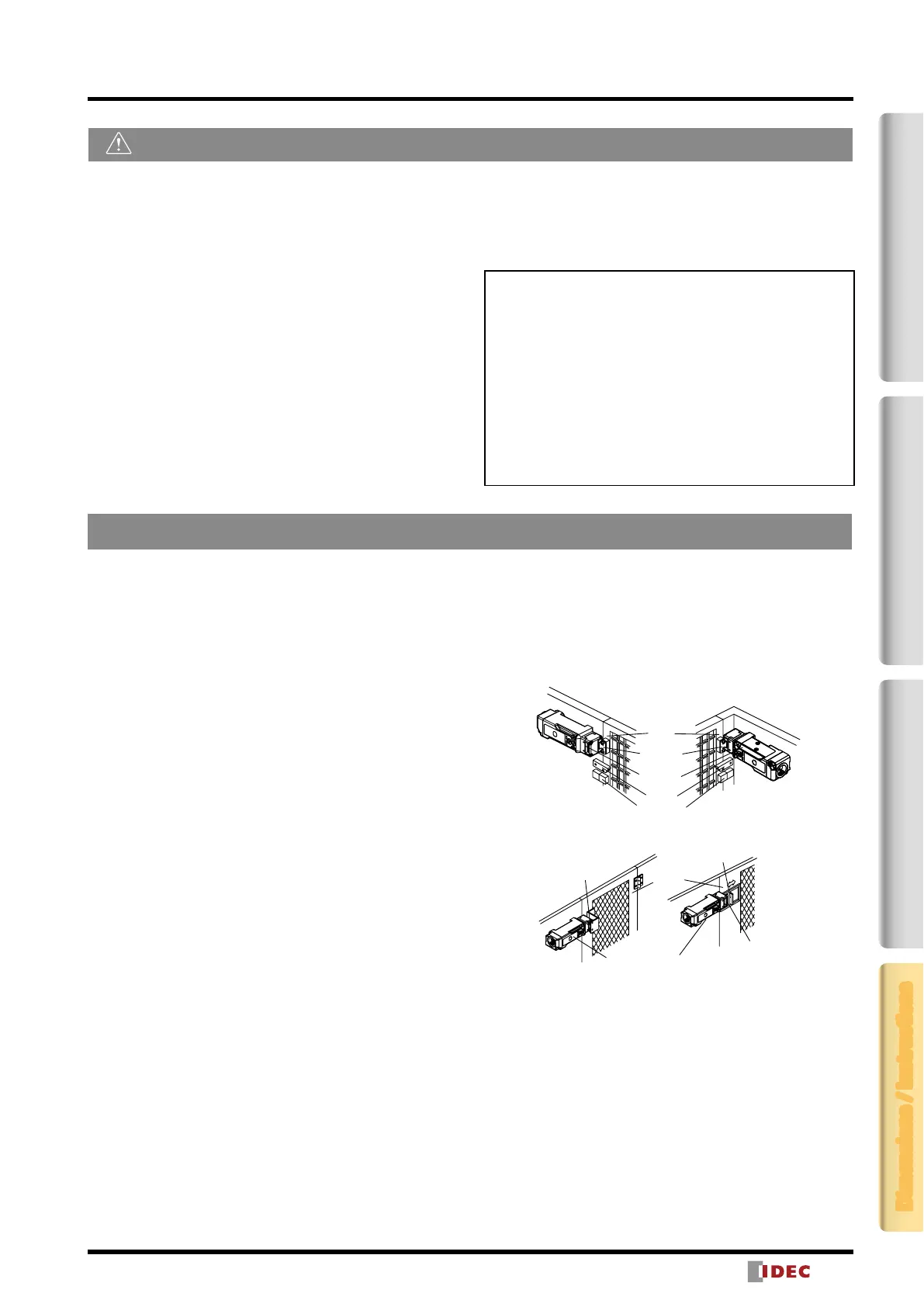
Mounting Examples
Refer to the following drawing for the installation. Mount the
interlock switch to a xed machine or guard, and actuator
on the hinged door. Do not mount both interlock switch and
actuator on the hinged doors. This may result in the actuator
being inserted at a wrong angle to the interlock switch,
resulting in malfunction.
Application of Sliding Doors
Door
HS9Z-A51
Actuator
HS5L
Interlock
Switch
Latch
Door Stop
Door
HS9Z-A51
HS9Z-A52
Actuator
Actuator
HS5L
Interlock Switch
Latch
Application of Hinged Doors
Instructions
2-Contact4-ContactActuatorDimensions / Instructions
 Loading...