22
HS5L Interlock Switches with Solenoid
Instructions
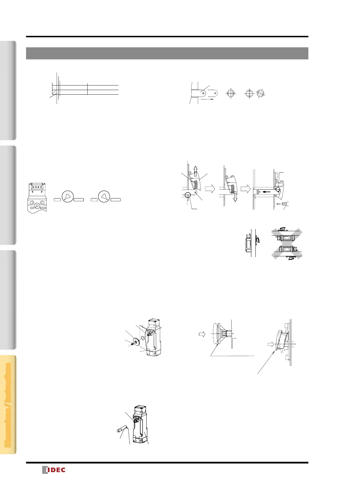
Manual Unlocking
Spring lock
The spring lock interlock switch allows manual unlocking of the
actuator to precheck proper door movement before wiring or
turning power on, as well as for emergency use such as a power
failure.
Solenoid lock
The solenoid interlock switch does not unlock even when the
solenoid is de-energized. However, the interlock switch can be
unlocked manually in emergency cases.
Normal Position
Manual Unlocking
Position
UNLOCKLOCKUNLOCKLOCK
UNLOCK
LOCK
When locking or unlocking the interlock switch manually, turn the
key fully using the manual unlock key supplied with the interlock
switch. Using the interlock switch with the key not fully turned
(less than 90°) may cause damage to the interlock switch or
operation failures (when manually unlocked, the interlock switch
will keep the main circuit disconnected and the door unlocked).
Do not apply excessive force to the manual unlock, otherwise the
manual unlock will become damaged. Do not leave the manual
unlock key attached to the interlock switch during operation.
This is dangerous because the interlock switch can always be
unlocked while the machine is in operation.
Safety Precautions
Before manually unlocking the interlock switch, make sure that the
machine has come to a complete stop. Manual unlocking during
operation may unlock the interlock switch before the machine
stops, and the function of interlock switch with solenoid is lost.
Installing the Rear Unlocking Button
(HS5L-L)
HS5L-L
Rear Unlocking
Button
Mounting
Screw
(M3 sems)
Panel
Push Rod
After installing the interlock switch on the
panel, place the rear unlocking button
(supplied with the switch) on the push
rod on the back of the interlock switch,
and fasten the button using M3 sems
screw (supplied with the switch).
When installing on a mounting frame
thicker than 6mm, use the rear unlocking button kit HS9Z-FL5
(sold separately).
Safety Precautions
After installing the rear unlocking button, apply Loctite to the
screw so that the screw does not become loose. The rod is made
of SUS, the button is made of glass-reinforced PA66 (66 nylon)
and the screw is made of iron. Take the compatibility of the plastic
material and Loctite into consideration.
Installing the Rear
Unlocking Button Kit
1. Install the connecting rod onto the
push rod on the HS5L-L rear
unlocking button interlock switch.
2. A pin is attached to the connecting
rod. Insert the pin into the hole in
the push rod, using pliers.
3. Pull the connecting rod from the hole in the mounting frame,
and turn the button operating pin to the horizontal position.
Correct
Incorrect
Connecting Rod Orientation
Pull
Connecting
Rod
Safety Precautions
• Ensure that the connecting rod is pulled out completely and it is
horizontal to the interlock switch, otherwise the unlocking button
cannot be installed.
Note: Frame must be supplied by the user.
For the mounting hole layout of interlock switches, see
dimensions on page 18.
4. Install the unlocking button on the connecting rod by tting the
pin to the grooves on the back of the button, and fasten the
base plate on the mounting frame using the screws.
B
A
Button
Operating
Pin
Button
Groove
(1) Pull up once
(2)
Unlocking
Button
5. After fastening the screws, check if locking and unlocking
operations can be performed.
Safety Precautions
Correct
orientation
Incorrect orientation
• Install the rear unlocking button
kit in the correct direction as
shown below. Do not install
the kit in incorrect directions,
otherwise malfunction may
occur.
• Do not apply strong force
exceeding 100m/s
2
to the
interlock switch while the rear unlocking button is not pressed,
otherwise malfunction may occur.
Unlocking the Manual Lock Using the
Rear Unlocking Button
Use the rear unlocking button when a worker is locked inside
a safety fence (hazard area). (Compliant with escape release
described in ISO14119 (2003) and GS-ET-19)
Unlock
Rear Unlocking Button
Unlock
Rear Unlocking
Button Kit
Procedure
• When the rear unlocking button is pressed, the interlock switch
is unlocked and the door can be opened.
• To lock the interlock switch, pull back the button.
• When the button remains pressed, the interlock switch cannot
be locked even if the door is closed, and the main circuit remains
open.
Safety Precautions
• Install the rear unlocking button in the place where only the
operator inside the hazardous area can use it. Do not install the
button in a place where an operator outside the hazardous area
can use it, otherwise the interlock switch can be unlocked during
usual machine operation, causing danger.
Lockable range
Maximum gap
[Reference] When using HS9Z-A51A with HS5L interlock switch:
23.1mm
Approx. 4.6mm Locking position
Approx. 4.6mm
Approx. 6.6mm Door close contact OFF
Approx. 4.6mm Locking position
Insert
Pull out
0
Approx. 6.6mm Door open contact ON
Approx. 8.2mm Door open contact ON
Approx. 8.2mm Door close contact OFF
∗ Approx. 4.6mm for HS9Z-A51A.
2-Contact4-ContactActuatorDimensions / Instructions
Connecting
Rod
Push Rod
HS5L-L
Interlock Switch
Pin
 Loading...