23
HS5L Interlock Switches with Solenoid
Instructions
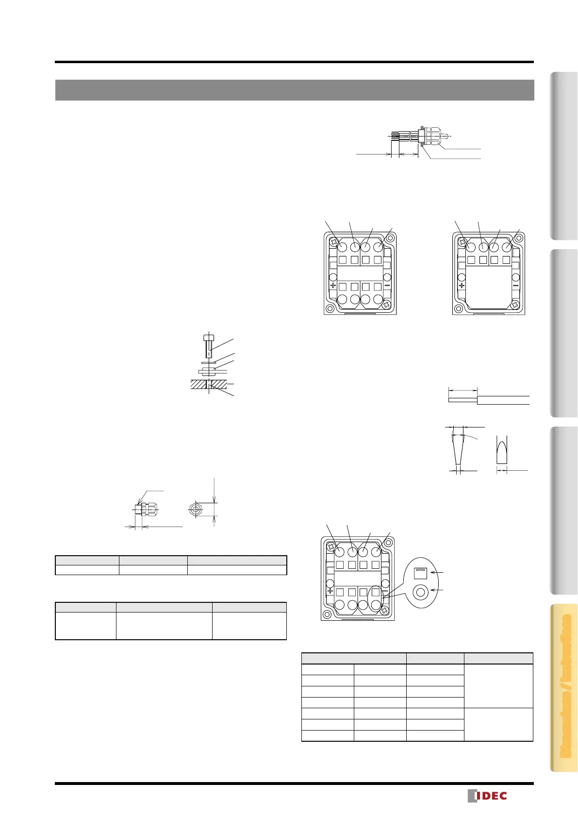
2-Contact4-ContactActuatorDimensions / Instructions
• Operate the rear unlocking button by hand only. Do not operate
using a tool or with excessive force. Do not apply force to
the button from the direction other than the proper direction,
otherwise the button will be damaged.
Recommended Tightening Torque
• HS5L interlock switch: 1.8 to 2.2 N·m (four M4 screws)*
• Lid mounting screw: 0.5 to 0.7 N·m (M3 screw)
• Rear unlocking button: 0.5 to 0.7 N·m (M3 screw)
• Rear unlocking button kit: 4.8 to 5.2 N·m (M5 screw)
• Actuators
HS9Z-A51: 1.8 to 2.2 N·m (two M4 screws)*
HS9Z-A52: 0.8 to 1.2 N·m (two M4 flat head screws)
HS9Z-A51A/A52A: 1.0 to 1.5 N·m (two M4 screws)*
HS9Z-A53: 4.5 to 5.5 N·m (two M6 screws)*
HS9Z-A55: 1.0 to 1.5 N·m (two M4 screws)*
HS9Z-BA5: 4.5 to 5.5 N·m (two M5 screws/four)*
* If the mounting screw recommended tightening torque values
above is not satised, check loosening after installation
throughly.
• Mounting screws need to be prepared by the customer.
• To avoid unauthorized or unintended removal of the interlock
switch and the actuator, it is recommended that the interlock
switch and actuator are installed in a secure manner, for example
using special screws or welding the screws (ISO14119).
• When installing the HS9Z-A51A
and HS9Z-A52A actuators, use the
washer (supplied with the actuator)
on the hinged door, and mount
tightly using two M4 screws.
Mounting centers: 12mm (factory
setting), adjustable to 20mm
Applicable Cable Glands
Use a cable gland with IP67 protection degree.
Applicable Cable Gland Dimensions
9mm max.
M20
30mm
max.
When Using Flexible Conduits (Example)
Flexible conduit example: VF-03 (Nihon Flex)
Conduit Port Size Plastic Cable Gland Metal Cable Gland
M20 — RLC-103EC20 (Nihon Flex)
When Using Multi-core Cables (Example)
Flexible conduit example: VF-03 (Nihon Flex)
Conduit Port Size Plastic Cable Gland Metal Cable Gland
M20
ST-M20X1.5*
(Manufacturer: LAPP)
(Distributor: K-MECS)
ALS-EC20
(Nihon Flex)
Different cable glands are used depending on the cable sheath
outside diameter. When purchasing a cable gland, conrm that the
cable gland is applicable to the cable sheath outside diameter.
* When using ST-M20X1.5, use with gasket below:
GPM20 (Manufacturer: LAPP Distributor: K.MECS)
Lead-in Wire Length and Wiring Examples
30 to 35
mm
8 to 9mm
Connector
Interlock switch
4-Contact
2-Contact
31/33/
51/53
32/34/
52/54
21/23
22/24
1211 4241
A1
A2
21/23/
41
22/24/
42
11/51
12/52
A1A2
Cautions for Wiring
Use the following applicable wiring.
Stranded wire or solid wire (1 wire):
0.3 to 1.5mm
2
(AWG22 to AWG16)
8 to 9mm
Incorrect Correct
Wire inserted to
the bottom
Insulation inserted
too deep
0.4
7º to 13
ø2.5
2.5
Make sure to strip the wire insulation 8
to 9mm from the end. If the strip
length is too short, the wire may fall
out. If the strip length is too long, it
may short circuit with other wires.
Twist the wires and make sure that
there are no wire whiskers.
When using stranded wires without
ferrules, make sure that the core wires
have not been loosened.
• For wiring, use screwdrivers as
shown in the right. (The shape of the
tip of the screwdriver is in accordance with DIN5264)
• The inserting port of the wire and screwdriver, and direction of
the tip is as shown in the diagram below.
31/33/
51/53
32/34/
52/54
21/23
22/24
12
11
4241
A1
A2
Screwdriver port
and direction of the
screwdriver tip.
Wire port
• When using ferrules for stranded wires, use the ferrule listed in
the following table.
Compatible Wire Model No. Manufacturer
0.34mm
2
AWG22 AI0.34-6TQ
Phoenix Contact
0.5mm
2
AWG20 AI0.5-6WH
0.75mm
2
AWG18 AI0.75-6GY
1mm
2
AWG18 AI1-6RD
0.5mm
2
AWG20 TE0.5-8
NICHIFU
Co., Ltd.
0.75mm
2
AWG18 TE0.75-8
1mm
2
AWG18 TE1.0-8
M4 Screw Hole
Hinged Door
Rubber
Bushing
Washer
(supplied)
Note: Choose mounting
centers of either
12mm or 20mm.
8 to 9mm
Incorrect Correct
Wire inserted to
the bottom
Insulation inserted
too deep
0.4
7º to 13
2.5
 Loading...