24
Instructions
HS5L Interlock Switches with Solenoid
Specications and other descriptions in this catalog are subject to change without notice.
Cat. No. EP1534-0 JANUARY 2015 PDF
IDEC ELECTRONICS LIMITED
Tel: +44-1256-321000, Fax: +44-1256-327755
E-mail: sales@uk.idec.com
IDEC ELEKTROTECHNIK GmbH
Tel: +49-40-25 30 54 - 0, Fax: +49-40-25 30 54 - 24
E-mail: service@idec.de
IDEC (SHANGHAI) CORPORATION
Tel: +86-21-6135-1515
Fax: +86-21-6135-6225 / +86-21-6135-6226
E-mail: idec@cn.idec.com
IDEC (BEIJING) CORPORATION
Tel: +86-10-6581-6131, Fax: +86-10-6581-5119
IDEC (SHENZHEN) CORPORATION
Tel: +86-755-8356-2977, Fax: +86-755-8356-2944
IDEC IZUMI (H.K.) CO., LTD.
Tel: +852-2803-8989, Fax: +852-2565-0171
E-mail: info@hk.idec.com
IDEC TAIWAN CORPORATION
Tel: +886-2-2698-3929, Fax: +886-2-2698-3931
E-mail: service@tw.idec.com
IDEC IZUMI ASIA PTE. LTD.
Tel: +65-6746-1155, Fax: +65-6844-5995
E-mail: info@sg.idec.com
IDEC ASIA (THAILAND) CO.,LTD.
Tel: +662-392-9765, Fax: +662-392-9768
E-mail: sales@th.idec.com
www.idec.com
IDEC CORPORATION (USA)
Tel: +1-408-747-0550 / (800) 262-IDEC (4332)
Fax: +1-408-744-9055 / (800) 635-6246
E-mail: opencontact@idec.com
IDEC CANADA LIMITED
Tel: +1-905-890-8561,
Toll Free: (800) 262-IDEC (4332)
Fax: +1-905-890-8562
E-mail: sales@ca.idec.com
IDEC AUSTRALIA PTY. LTD.
Tel: +61-3-8523-5900, Toll Free: 1800-68-4332
Fax: +61-3-8523-5999
E-mail: sales@au.idec.com
6-64, Nishi-Miyahara 2-Chome, Yodogawa-ku, Osaka 532-0004, Japan
Tel: +81-6-6398-2527, Fax: +81-6-6398-2547
E-mail: marketing@idec.co.jp
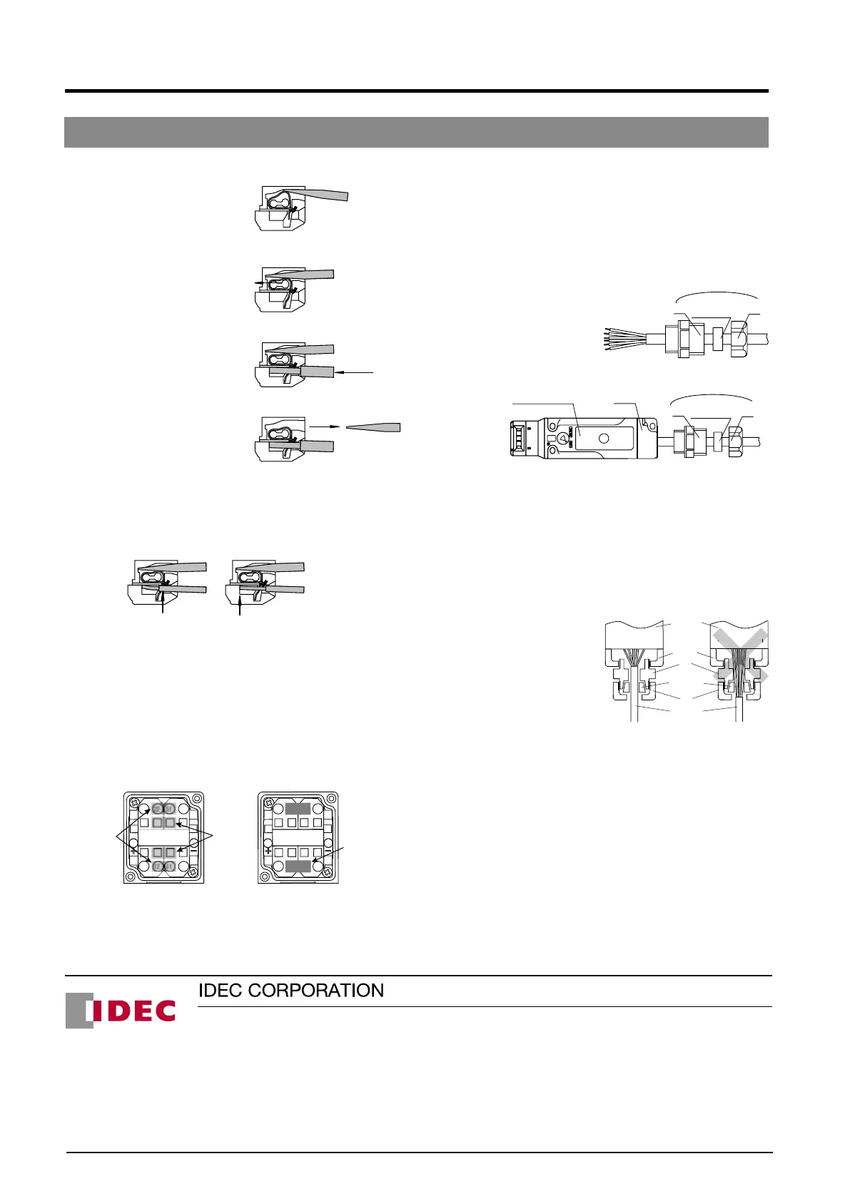
Wire connection method
1. Insert the screwdriver into
the square-shaped port from
a slightly slanted angle as
shown, until the screw-driver
tip touches the bottom of the
spring. Make sure that the
direction of the blade edge is correct.
2. Push in the screwdriver until it
touches the bottom of the port.
The wire port is opened, and the
screwdriver is held in place.
The screwdriver will not come
off even if you release your hand.
3. While the screwdriver is retained
in the port, insert the wire or
ferrule into the round-shaped
wire port.
4. Pull out the screwdriver. The
8 to 9mm
Incorrect Correct
Wire inserted to
the bottom
Insulation inserted
too deep
0.4
7º to 13
ø2.5
2.5
connection is now complete.
Safety Precautions
When using wires with insulation diameter of ø2.0mm or less, do
not insert the wire too deeply where the insulation inserts into
the spring clamp opening. Make sure that the wire insulation is
stripped 8 to 9mm and the wire is inserted to the bottom.
If there is a need to insert the screwdriver while holding the
interlock switch with hands, be careful not to injure your ngers
with the tip of the screwdriver.
Connect one wire to one wiring port.
(According to IEC 60204 (JIS 9960-1) 13.1.1 General Requirement)
Installing the HS9Z-JP5L Jumper
HS9Z-JP5L is used on a 4-contact interlock switches to connect
the door monitor circuit (11-12) / (21-22) in series with the lock
monitor circuit (41-42)/(51-52) for safety circuit input.
For example, when wiring 12 and 41:
11 42
A1
A2
21 52
11 42
A1
A2
21 52
Screwdriver
port
Insert the
jumper into
the wiring
port
12-41
connected
using jumper
1. As shown in the gure on the left above, insert a screwdriver in
the screwdriver ports.
2. Insert the jumper completely in wiring ports 12 and 41.
3. Pull out the screwdriver. The wiring of the jumper is complete.
Safety Precautions
• For circuit code DD, a jumper is wired between 12-41 and 22-51
at factory setting.
• Be sure to connect only to 12-41 and 22-51.
Connector Wiring
Perform wiring according to following procedures 1. to 4.
1. Insert the cable into the connector. Leave A and B untightened.
2. Open the cover and insert the cable into the cover.
Interlock switch Cover
A
B
A
Waterproong
gasket
Waterproong
gasket
B
Connector (sold separately)
Connector (sold separately)
3 Wire to the terminals.
4 Tighten in the order of A → Cover → B.
* To remove the wiring, turn the power off and then unwire in the
order of B → cover (→waterproof gasket → A).
Note: When removing A, because the waterproong gasket is
tightly attached to the cable, pull out the gasket carefully
with tweezers so that the gasket is not damaged before
loosening A. Otherwise, the cable will rotate together with A
when loosened, and might break due to excessive twisting.
Also, when reassembling, place the gasket in the original
position rst.
Safety Precautions
Interlock
switch
Spring clamp
terminal block
Spring clamp
terminal block
A
Waterproong
packing
Sheath
B
Cover
Gasket holds
the sheath
tightly
Make sure that the entire bore
surface of the gasket is in contact
with the sheath.
Sheath is
loose
• When opening the cover, be
careful not to lose the cover
mounting screw.
• When tightening connector
B, insert the cable into the
connector, and set it to a
position where the gasket
of the connector holds the
cable sheath, otherwise, its
waterproof performance might
be impaired.
• Tighten the connector in
order of A → B. If connector
B is tightened rst, the wiring
connected to the spring
clamp terminal may become twisted when tightening A, causing
disconnection or malfunction.
• Tighten the connectors with tightening torque according to the
torque value recommended by the connector manufacturer.
Otherwise, waterproof performance might be impaired.
• Do not exert excessive load, pressure, or tensile force on the
cable, otherwise, disconnection or malfunction might occur.
8 to 9mm
Incorrect Correct
Wire inserted to
the bottom
Insulation inserted
too deep
0.4
7º to 13
ø2.5
2.5
8 to 9mm
Incorrect Correct
Wire inserted to
the bottom
Insulation inserted
too deep
0.4
7º to 13
ø2.5
2.5
8 to 9mm
Incorrect Correct
Wire inserted to
the bottom
Insulation inserted
too deep
0.4
7º to 13
ø2.5
2.5
Incorrect Correct
Wire inserted to
the bottom
Insulation inserted
too deep
 Loading...