18
HS5L Interlock Switches with Solenoid
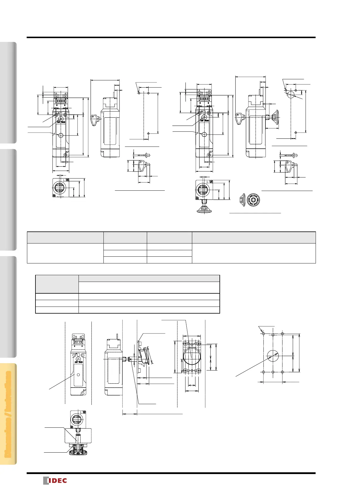
HS5L-
4
-G (with Indicator)
When using Horizontal Mounting / Straight Actuator (HS9Z-A51)
LED
(with Indicator)
Manual Unlocking Key (supplied)
Manual Unlock
Mounting Hole Layout
36.2
9
44.5
127
R2.2
20
11
29.2
5.2 6.2
42.2
5
11
35
30
86.5
10
1
20
40
34
86.5
10 to 11
20 to 22
3
(24)
915
18 6.5
(24.5)
3
3-M4 Screw
HS5L-
4
-G (with Indicator)
When using Horizontal Mounting / Straight Actuator (HS9Z-A51)
Rear Unlocking Button (supplied)
36.2
9
44.5
127
R2.2
20
11
29.2
5.2 6.2
42.2
5
11
35
30
86.5
10
1
20
40
34
86.5
10 to 11
7.7
27
3
(24)
915
18
6.5
(24.5)
3
9
ø14
LED
(with Indicator)
Manual Unlock
20 to 22
Manual Unlocking Key (supplied)
Mounting Hole Layout
3-M4 Screw
Accessories
Description Part No. Package Quantity Remarks
Rear Unlocking Button Kit (Note)
HS9Z-FL53 1
Panel Thickness * (X) HS9Z-FL54 1
HS9Z-FL55 1
Note: See table below when selecting rear unlocking button kit.
Part No.
Panel Thickness * (X)
HS5L Interlock Switch Rear Unlocking Button Kit
(When mounting HS5L- L directly)
HS9Z-FL53
23
< X ≤ 33
HS9Z-FL54
33
< X ≤ 43
HS9Z-FL55
43
< X ≤ 53
ø22 to 30
Rear Unlocking
Button Hole (Note)
16 to 30
3325.5
60.5
M5 Screw
Button (PA66)
Panel Thickness (X): 23 to 53
73
60.5
33
16
30
31.5
25.5
ø40
40
ø10.4
Pin (SUS)
Link Rod
(SUS)
Screw (Iron)
Hinge + Plate
(SUS)
Button released
Button pressed
(unlocked)
HS5L
Interlock Switch
(sold separately)
Rear Unlocking Button Kit
Mounting Hole Layout
All dimensions in mm.
Note: With the mounting hole dimension, the rear unlocking button rod does not touch the hole even when the interlock switch moves sideways.
2-Contact4-ContactActuatorDimensions / Instructions
Interlock Switch Dimensions and Mounting Hole Layouts
All dimensions in mm.