17
Horizontal / Vertical Actuator Orientation
Horizontal Swing Vertical Swing
The orientation of actuator swing (horizontal/vertical) can be changed using the orienting insert (white
plastic) installed on the back of the actuator. Attach the orienting insert if necessary. (See left diagram)
Do not lose the orienting insert, otherwise the actuator will not operate properly.
Actuator Mounting Reference Position
HS9Z-A52
Actuator
Actuator Cover
Actuator Stop
Interlock Switch
Door Stop
HS9Z-A51
Actuator
Actuator Stop
Door Stop
As shown in the gure on the right, the mounting reference
position of the actuator when inserted in the interlock switch
is the position where the actuator stop placed on the actuator
lightly touches the side surface of the interlock switch.
Note: After mounting the actuator, remove the actuator stop from the
actuator.
Accessory Dimensions and Mounting Hole Layouts All dimensions in mm.
Spring Loaded Actuator (HS9Z-BA5)
Mounting Hole Layout
HS5L Interlock Switch with Actuator
Body (SUS)
7
2.5
7
15
7
23
5
15
31
41
40
58
11.3
3
35.1
47
3.3mm line
0.8mm line
Lock limit line
Mounting tolerance
range: ±1.0
±0.75
6-M5
Screw
10 to 15
10 to 15
47
∗ When the actuator is installed on the same plane
as the HS5L interlock switch, because the height
of the actuator will be 5mm lower than the
interlock switch, adjustment is required by the
customer.
0.8
(Mounting tolerance range: 0.8 )
+2.5
0
∗5±0.5
(Height adjustment)
86.5
36.2
47
20 to 22
A
B
C
57
Actuator (SUS)
Thickness: 2.5
Mounting
tolerance range
Fasten at least four parts (either
A or C, and B in the drawing on
the right) with mounting screws.
Always fasten B to prevent
movement during use.
Actuators for HS5 Series Interlock Switches
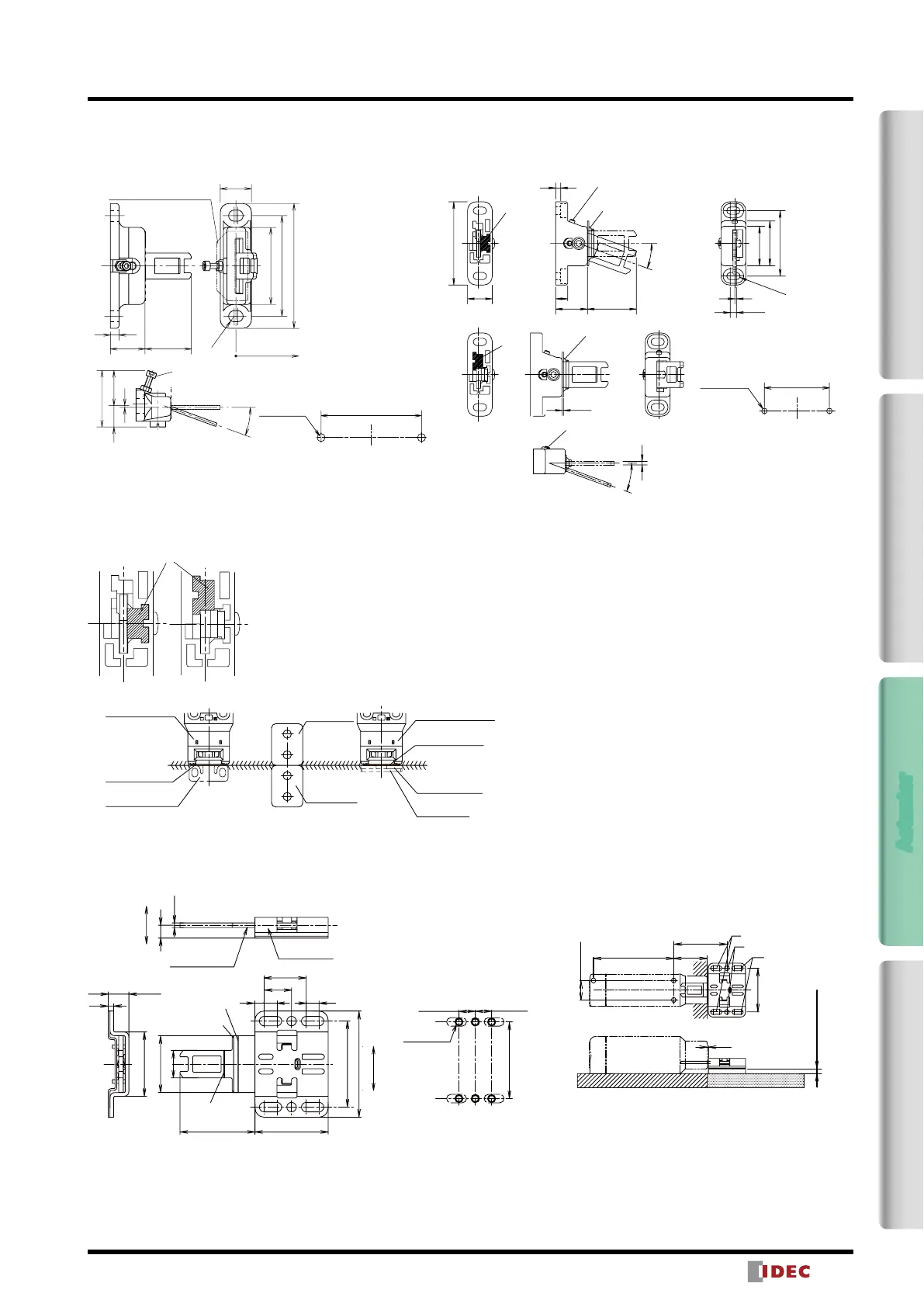
Actuator Dimensions and Mounting Hole Layouts All dimensions in mm.
Angle Adjustable (vertical) (HS9Z-A53)
20
5
R3.2
72
58
44
33 max.
12 (21)
1
20°
29
58
2-M6 Screw
18
Actuator Mounting Hole Layout
(Angle Adjustable (vertical))
Angle Adjustment
(M3 hexagon socket head bolt)
Door Hinge
Side
(supplied with the actuator)
Note: The actuator stop lm and actuator stop are supplied with the
actuator and used when adjusting the actuator position. Remove
after the actuator position is determined.
Angle Adjustable (vertical/horizontal) (HS9Z-A55)
15 7
18.5 29
3
(M4 Hole)
3.6
1
R2.1
23
26
38
38
0.8
2
20゚
20゚
Note: Actuator Stop Film
(supplied with the actuator)
Note: Actuator Stop Film
(supplied with the actuator)
Angle Adjustment
(M3 hexagon socket head bolt)
Angle Adjustment
(M3 hexagon socket head bolt)
(Horizontal Swing)
(Vertical Swing)
Orienting
Insert
Orienting
Insert
2-M4 Screw
Actuator Mounting Hole Layout
(Angle Adjustable (vertical/horizontal))
2-Contact4-ContactActuatorDimensions / Instructions
 Loading...