65
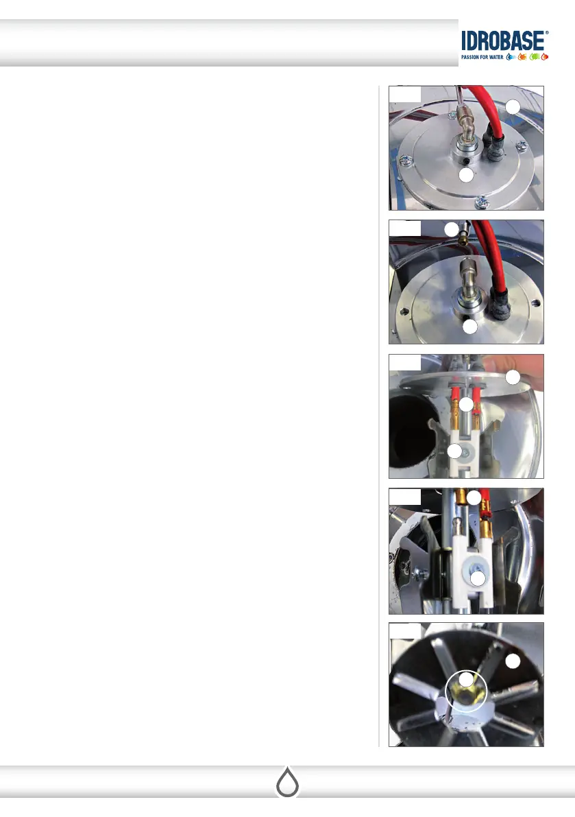
Fig. 2
Fig. 4
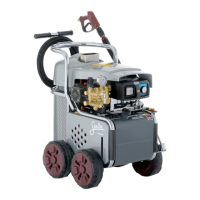
Fig. 1
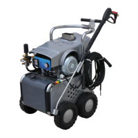
Fig. 3
Fig. 5
A
B
B
F
F
B
G
B
D
E
C
ELECTRODES AND FUEL NOZZLE MAINTENANCE
T2000/2 has been designed to enable thinking to the safety of operators and to let an
easy maintenance.
The combustion head is an example of it: it is realized to avoid the direct contact with
electrodes which are inside the heater. It make pratically impossible to touch elec-
trodes and clutches of high tension cables with hands or metal parts. All this is very
pratical in the maintenance, simply unscrewing and removing the complete combu-
stion head.
1. Fig. 1 showns the cover (A) of the heater in which is xed the combustion head
(B). On the combustion head are located electrodes (C) and fuel nozzle (D).
2. Remove the fuel supply pipe (E) as show in g. 2, and unscrew 4 xing screws.
3. Remove the head combustion group (g. 3).
4. To replace the electrodes (C) (g. 4):
• Remove the red high cable tension (F) that connects the ignition transformer
to the electrodes (C).
• Remove the screw (G) that xes the electrodes to the combustion head.
5. To clean the fuel lter nozzle (D) or to replace it (g. 5):
• Provide the key to remove the fuel nozzle (D) from the combustion head (B).
• Remove the fuel nozzle and clean or replace the fuel lter or the complete fuel
nozzle..
9 MAINTENANCE
Copyright ©2016 Idrobase Group. All rights reserved.