5
SMS Duo Manual 700-558-01D
THANK YOU FOR CHOOSING IDS TO PROTECT YOU
Congratulations on your purchase of the IDS SMS Duo module. IDS systems are powerful, versatile and highly configurable systems, which should
be installed by a professionally trained installer.
This manual covers the installation of the SMS Duo module. For IDS805 programming please refer to the IDS805 User Manual
Features
Two Zone Inputs 3k3 ohm end of line supervised
Two relay outputs
Can be connected to an IDS805
IDS805 integration reports communication fail if SMS Duo losses communication with the IDS805
Can operate as a standalone unit
Function
The SMS Duo unit has been designed to work with the IDS805 alarm panel as a virtual keypad or as a standalone system with 2 inputs and 2
outputs.
IDS805 Integration
The SMS Duo connects to the IDS805 keypad bus as a second keypad and supports the following functionality:
Away Arm, Stay Arm and Arm Status
Disarm
Zone bypass, Unbypass and Bypass Status
Zone status
SMS Duo PGM triggering, on/off, pulse high/low and status
Event reporting
Arm and disarm
Bypass and unbypasses
Zone violations while the system is armed
Panic and fire
Tampers
System Troubles
Please refer to the connection diagram, see figure 2 on page 9, at the end of the manual for wiring information.
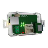
The LED on the interface board will come on when the module has power and has received a valid Clock and Date pulse from the IDS805 alarm, see
figure 2 on page 9.
Standalone Operation
The SMS Duo can operate in standalone mode and supports the following functions.
Monitoring of two 3k3 ohm end of line supervised inputs
Triggering two outputs
Outputs
The outputs on the interface board are relay driven outputs which can be triggered in four different ways:
Latched high.
Output will change from open to closed and remain until a sms is received to return to the open state
Latch Low
Used once the Latch high command has been sent, to return the output to the open state
Pulse High
The output will change from the open state to the closed state and return back to the open state after 3 seconds.
Pulse Low
The output must be in the closed state and will change to the open state and return back to closed state after 3 seconds
Inputs
The inputs monitor for an open or closed condition. 3k3 ohm end of line resistors are required. A 3k3 resistor must be connected in series with a
normally-closed type of input, and in parallel with a normally-open type of input. Applicable messages will be sent as zone 9 and zone 10.
Phone Numbers
There are three groups of user phone numbers. Entering phone numbers into the SMS unit is done via SMS’s from a “Master Phone Number”.
In the default state any cell phone can be used to enter the first “Master Phone Number”, once entered the phone with that cell number must be
used to enter more cell numbers or control the system.
Master Phone Number
Master phone numbers have the highest level of access to the SMS Module. Master phone numbers are allowed access to all configuration
data. Only master numbers are permitted to add phone numbers to the system and allocate which partitions will report to each phone
number.
Arming phone Numbers
Arming phone numbers are the second level of phone numbers. These phone numbers are permitted user rights to be able to control the
Alarm Panel and receive reports.
Reporting Phone Numbers
Reporting phone numbers are at the lowest level, and access to the SMS Module is restricted to only receiving reports.