8
SMS Duo Manual 700-558-01D
Zones Bypassing
The “Bypass” command will be sent to bypass specific zones. You must specify which zones to bypass in the data field. Zones may be referred to by
their number or, where applicable, by their name.
Valid Extended Commands:
Status – Returns the bypassed status of the zone(s).
Bypass named zone “Passage”
Bypass named zone “Lounge” &
“Kitchen”
Retrieve status of zone 1
Retrieve status of “Lounge”
NOTE: Zones can only be bypassed if the alarm is unarmed
Zone Unbypassing
The Unbypass command is sent when a zone is bypassed and you want to reactivate it.
NOTE: Zones can only be unbypassed if the alarm is unarmed
Programmable Outputs
PGM command controls the programmable outputs on the ESMS Duo interface board labelled RLY1 and RLY2. These are relay outputs that are in
the normally open state by default. The outputs do not supply any voltage
The PGM that is to be controlled must be specified in the data field and what action it must perform in the extended command field.
PGMs may be named with this command as well. As such, PGMs may be referred to by their number or their name.
Valid Extended Commands:
On – Changes the relay from open to closed
Off – Changes the relay from closed to open
PulseH – Pulse High changes the output relay from open to closed for 3 seconds before returning it back to the open state
PulseL – Pulse Low changes the output relay from closed to open for 3 seconds before returning it back to the closed state
Status – Queries the state of the output
Name – Each output can be given a more meaningful name for easier control
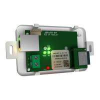
GSM Module Status LEDs
See figure 1: X-SMS Module below for LED locations
GSM Connect Status
LED flashes once per second if not connected and once every three seconds when connected to the Cell network and the signal strength is good
enough to communicate.
Heart Beat
LED Flashes when the unit is running and the power up sequence has completed.
Network Status
LED Flashes when connected to the Cell provider’s network and accepted by the service provider. I.E. Sim card is activated
Network Comms
LED on when communicating with the Cell network
I/O Module Panel Comms
LED on when communicating with the Interface board
Interface Board LED
Panel Comms LED (See Fig 1 to 3)
Slow flash – IDS805 not detected on power up and SMS Duo in Stand Alone Mode
On – IDS805 detected and in IDS805 Mode
Off – IDS805 disconnected (Only shows if an IDS805 was connected and then disconnected.) To engage standalone mode power down then up.