Do you have a question about the IDTECK Star 505R and is the answer not in the manual?
Details on the capabilities and functions of the Star 505R access controller.
Technical specifications including CPU, memory, user capacity, and read range.
Details on Stand-Alone, Host Computer, Data Backup, Keypad, Anti-Pass-Back, I/O, Time/Holiday Schedules, and Alarms.
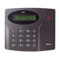
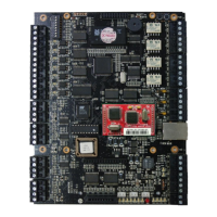
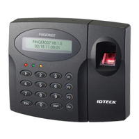
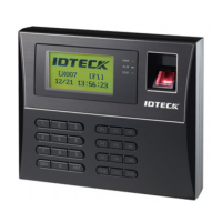
Explanation of the product, including front panel components and their functions.
Table mapping signal names to wire colors for various connections.
Pre-installation checks including cable selection and recommended types.
Installation checks like termination resistors and connection methods.
Guidelines for proper grounding of communication cables to prevent noise.
Explains the need for a reverse diode for inductor protection against surge voltage.
Physical dimensions of the Star 505R unit in millimeters and inches.
Instructions for setting the backup battery DIP switch for memory retention during power failure.
Steps for initializing the system, including hardware initialization.
Instructions for mounting the unit using a wall bracket and template.
Detailed instructions for wiring power, input devices, and output devices.
Instructions for connecting additional proximity readers and compatible models.
Steps for connecting the unit to a host PC via RS232 communication.
Instructions for RS422 communication setup, for single and multiple units.
Reference to the software manual for dial-up modem setup.
Reference to the software manual for TCP/IP converter setup.
Steps for initializing the 505R unit, including hardware initialization.
Guide on accessing the setup menu using Master ID and function keys.
Procedure for setting the device's date and time, including day codes.
Configuration of the maximum number of user IDs that can be registered.
Procedure for registering user IDs via RF cards or keypad input.
Description of normal operation modes including power on, card reading, exit button, and alarms.
Information on resetting the controller to factory default settings.
Settings for Reader mode, Time, APB, Comm Address, Baud Rate, Event Clear, Master ID, System Initialize.
Settings for Time Schedule, Holiday, In/Out Define, Holiday Index, Mode Index, LCD Display, Output Time Set.
Settings for ID Registration, ID Delete, ID List, Registered ID Count, ID Count.
Settings for Version, SRAM Test, Output Test, LCD Test, Keypad Test, Reader Test, Input Test, Comm Test.
Table showing default output settings for various input signals.
Troubleshooting abnormal operation, LCD display problems, and setting value changes after power reset.
Resolving issues like unregistered cards, inability to enter Setup, PIN access failures, and mode settings.
Addressing reader response issues, buzzer sounds, error messages, and controller-host communication failures.
Information regarding FCC compliance, operating conditions, and interference correction.
Details on the warranty periods for different components of the product.
Form for requesting Return Merchandise Authorization (RMA) for repairs or replacements.
Template for marking drill holes for wall mount installation.
| Operating Temperature | -20 ~ 50℃ |
|---|---|
| Reader Input | 2 |
| CPU | 32-bit RISC |
| Memory | 8MB Flash, 8MB SDRAM |
| Communication | TCP/IP, RS485 |
| Reader Port | 2 |
| Wiegand | 26/34bit Wiegand |
| Relay | 2 |
| Operating Voltage | 12VDC |
| Input Voltage | 12VDC |