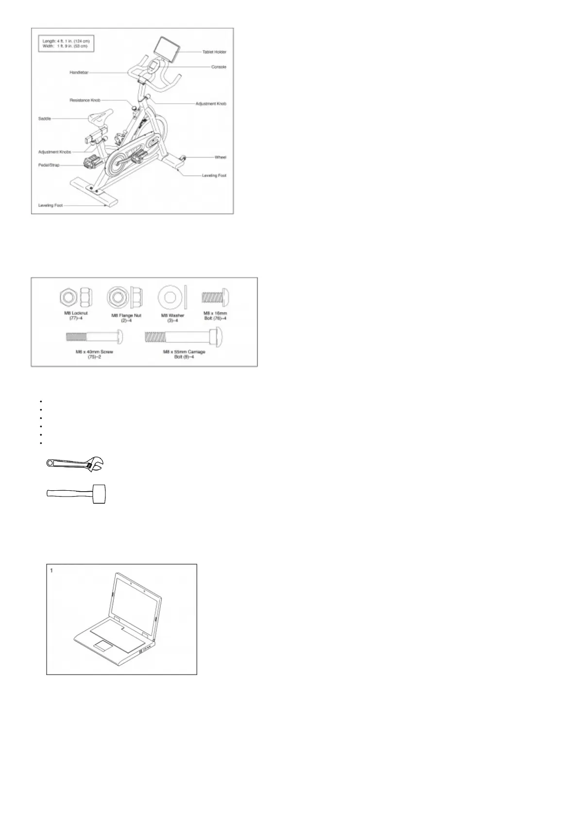
PART IDENTIFICATION CHART
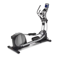
Use the drawings below to identify the small parts needed for assembly. The number in parentheses below each drawing is the key number of the part, from the PART LIST near the
end of this manual. The number following the key number is the quantity needed for assembly. Note: If a part is not in the hardware kit, check to see if it has been
preassembled. Extra parts may be included.
ASSEMBLY
To hire an authorized service technician to assemble this product, call 1-800-445-2480.
Assembly requires two persons.
Place all parts in a cleared area and remove the packing materials. Do not dispose of the packing materials until you finish all assembly steps.
Left parts are marked “L” or “Left” and right parts are marked “R” or “Right.”
To identify small parts, Check above.
In addition to the included tool(s), assembly requires the following tool(s):
one adjustable wrench
one rubber mallet
Assembly may be easier if you have a set of wrenches. To avoid damaging parts, do not use power tools.
1. Go to my.proform.com on your computer and register your product.
• documents your ownership
• activates your warranty
• ensures priority customer support if assistance is ever needed
Note: If you do not have internet access, call Customer Care (see the front cover of this manual) and register your product.
2. If there are shipping tubes (not shown) attached to the front and rear of the Frame (1), remove and discard the shipping tubes and the hardware attaching them.
Orient the Front Stabilizer (4) as shown.
Attach the Front Stabilizer (4) to the Frame (1) with two M8 x 55mm Carriage Bolts (9), two M8 Washers (3), and two M8 Flange Nuts (2).