Do you have a question about the IFM efector 300 SI5010 and is the answer not in the manual?
Explains the calorimetric measuring principle for flow monitoring and output switching.
Guidance on selecting the optimal installation site and orientation for accurate flow measurement.
Identifies factors in the pipe system that can cause turbulence and affect unit performance.
Step-by-step instructions for physically mounting the device securely and correctly.
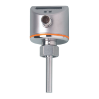
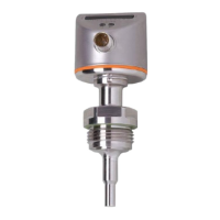
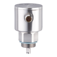
The ifm electronic efector300 SI5010 is a flow monitor designed for reliable monitoring of liquid and gaseous media. This device operates on a calorimetric measuring principle, detecting flow speed and providing a switching output based on the presence or absence of medium flow.
The primary function of the SI5010 is to monitor flow speed. By default, the unit's output is normally open, meaning the output closes when medium is flowing and opens when there is no flow. This behavior can be reconfigured to normally closed if needed, in which case the output opens when medium is flowing.
The switching status of the device changes when the flow speed reaches a predefined switch point. If the flow speed increases and crosses the switch point, the output changes its status. Conversely, if the flow speed falls, the output changes status when the value "SP minus hysteresis" is reached. The hysteresis is dynamic, adjusting with the flow speed and the set monitoring range. For instance, in the factory setting range of 5 to 100 cm/s, the hysteresis is typically 2 to 5 cm/s, increasing with higher flow speeds.
The unit offers a typical response time of 1 to 10 seconds, which can be influenced by the switch point setting. A low switch point results in a quicker reaction to rising flow, while a high switch point leads to a quicker reaction to falling flow.
Beyond basic flow monitoring, the SI5010 supports bidirectional communication via IO-Link. This allows for remote evaluation of process data and remote parameter setting, including adjustment of the output function. Device-specific parameter lists for IO-Link are available for detailed configuration.
The SI5010 is designed for ease of installation and setup, with several features to optimize its use in various applications.
The unit can be adapted to different process connections using ifm adapters, which must be ordered separately. Proper fit and ingress resistance are ensured when using ifm adapters. For small flow rates, ifm adapter blocks are available. Key installation guidelines include ensuring the sensor tip is completely surrounded by the medium, with a minimum insertion depth of 12 mm. Recommended mounting for horizontal pipes is from the side, and for vertical pipes, in the rising pipe. Conditional mounting for horizontal pipes from the bottom is acceptable if the pipe is free from build-up, and from the top if the pipe is completely filled with medium. It is crucial to avoid contact between the sensor tip and the pipe wall, and the unit should not be mounted in downpipes that are open at the bottom. During mounting, the system must be free of pressure, and no media should leak at the mounting location. The threads of the process connection, adapter, and nut should be greased, taking care to prevent grease contact with the sensor tip. The suitable adapter is screwed into the process connection, and the flow monitor is placed onto the adapter and tightened with a torque of 25 Nm, ensuring correct orientation.
The unit must be connected by a qualified electrician, adhering to national and international regulations for electrical equipment installation. Voltage supply should conform to EN 50178, SELV, PELV. Power must be disconnected before connecting the unit. The wiring includes L+, Teach, OUT1/Data, and L-. OUT1/Data serves as the switching signal for the flow limit value and as a data channel for bidirectional communication, while Teach is for the teach signal.
The device features an operation display with green LEDs (0 to 9) indicating the current flow within the range from no flow to maximum flow. A lighting LED indicates the switch point position (orange for output closed, red for output open). Setting buttons are provided for adjustment and configuration.
Upon power-on, all LEDs light up and go out step by step, during which the output is closed (if configured as normally open), and the unit enters operating mode. The normal flow should be circulated in the installation, and the display checked for further actions. If the factory setting is suitable (LED 1 display), no further settings are required. If normal flow is below the display's representation range (LED 2 display), the switch point can be changed or high flow adjustment performed. If normal flow exceeds the display's representation range (LED 3 display, LED 9 flashes), high flow adjustment should be carried out. The factory setting can be restored at any time.
The factory switch point is at LED 7. A change is beneficial if the display shows example 2, if flow fluctuates significantly, or if a faster response time is desired. Briefly pressing the setting buttons causes the switch point LED to flash, and further presses shift the LED position. If no button is pressed for 2 seconds, the unit returns to operating mode with the new value.
This adapts the display representation to the existing normal flow. The normal flow is circulated, and a specific button is pressed and held. LED 9 lights up and then flashes after approximately 5 seconds. Releasing the button adapts the unit to the flow conditions, and the display should show example 1. This adjustment proportionally increases the switch point up to LED 7.
This is used when the unit monitors media other than water and should be performed after high flow adjustment. The minimum flow is circulated or flow standstill is ensured. A specific button is pressed and held. LED 0 lights up and then flashes after approximately 5 seconds. Releasing the button adopts the new value, and the unit enters operating mode.
The unit is delivered as normally open. To change to normally closed, a specific button is pressed for at least 15 seconds. LED 0 lights up and flashes after 5 seconds. After 10 seconds, the current setting is displayed (LEDs 5-9 orange for normally open). After 15 seconds, LEDs 0-4 flash orange, indicating the output is changed to normally closed. Repeating the operation reverts the setting.
Pressing a specific button for at least 15 seconds will reset all settings to factory defaults: operating area (5-100 cm/s for water), switch point (LED 7), output function (NO), and unlocked status.
To prevent unintentional settings, both setting pushbuttons can be pressed simultaneously for at least 10 seconds in operating mode. The indication goes out, and the unit locks or unlocks. The unit is unlocked on delivery.
The unit can be adapted to new flow conditions remotely by applying operating voltage for specific durations to Pin 2 for high flow adjustment (5 to <10 s) or low flow adjustment (10 to <15 s). This adjustment does not affect the relative position of the switch point.
If adjustment fails, all LEDs flash red, and the unit returns to operating mode with unchanged values. Possible causes include installation errors (refer to chapter 4), insufficient difference between maximum and minimum flow (requiring increased flow difference for re-adjustment), or incorrect sequence of high flow/low flow adjustment (requiring re-execution in the correct order).
After power-on, the unit performs a self-check (LEDs light up and go out) and is ready for operation. All settings are retained during power failure or interruption. Operating indicators include a green LED bar for current flow, orange/red LEDs for switch point indication (output closed/open), flashing LED 9 for current flow above the representation range, and flashing LED 0 for current flow far below the representation range. An interference indicator shows alternating operating and red LEDs for a short circuit at the switching output. Once rectified, the unit returns to normal operation. If the display is off (no LEDs light), it indicates operating voltage is too low (<19 V) or failed, requiring a correct voltage supply.
Regular maintenance ensures the longevity and optimal performance of the SI5010. It is recommended to periodically check the sensor tip for any build-up. The sensor tip should be cleaned using a soft cloth. For stubborn build-up, such as lime, a common vinegar cleaning agent can be used effectively.
| Protection class | IP 67 |
|---|---|
| Supply voltage | 18...30 V DC |
| Output type | Analogue |
| Electrical design | PNP/NPN |
| Output function | Normally open / Normally closed |
| Electrical connection | M12 |
| Operating temperature | -25...70 °C |
| Storage temperature | -40...100 °C |
| Housing material | Stainless steel |
| Media temperature | -25...70 °C |
| Measuring range | 3...300 cm/s (water); 200...3000 cm/s (oil) |