7
UK
5 Electrical connection
The unit must be connected by a qualified electrician�
The national and international regulations for the installation of electrical
equipment must be adhered to�
Voltage supply to EN 50178, SELV, PELV�
► Disconnect power�
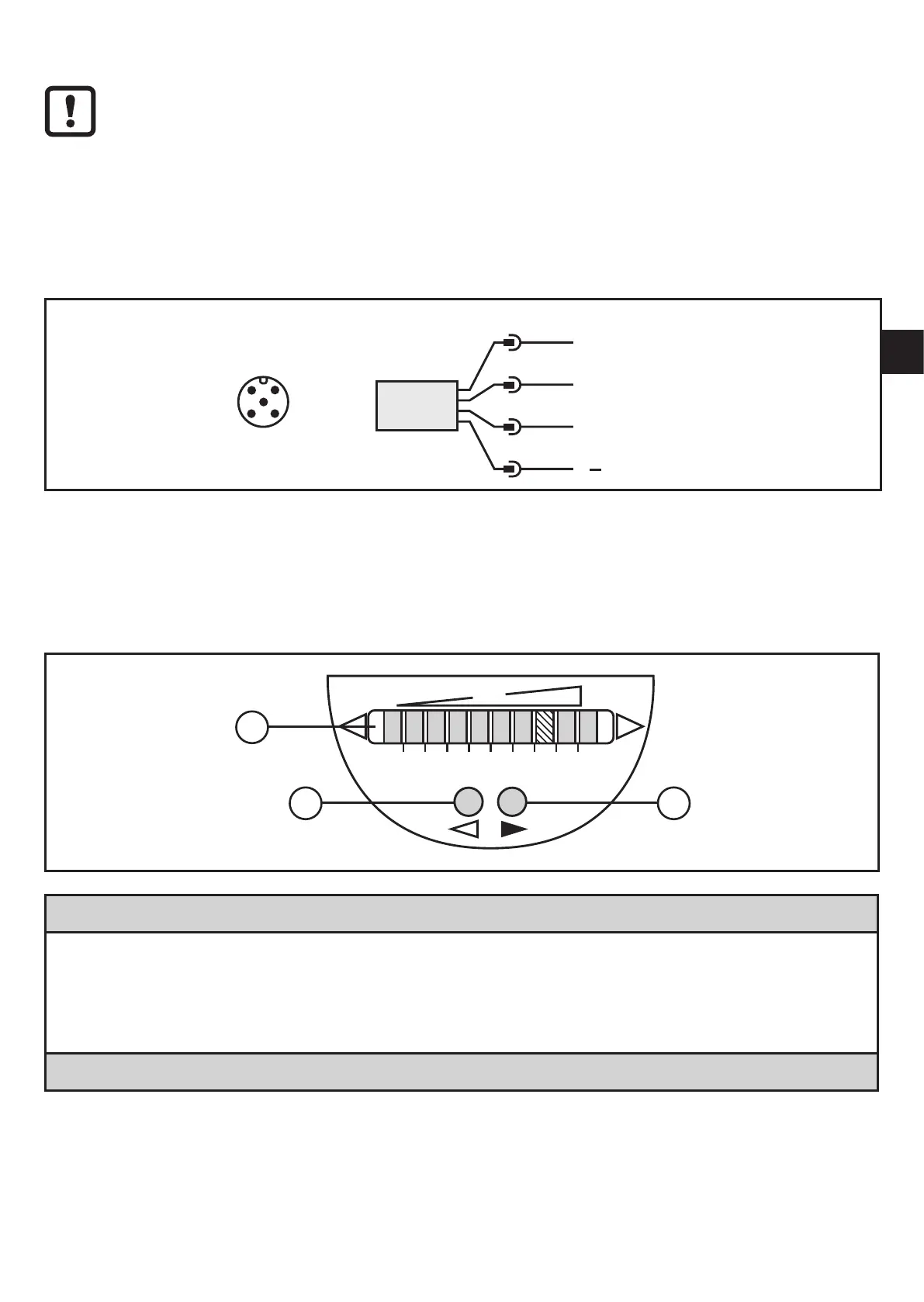
► Connect the unit as follows:
4
2 1
3
4
1
3
2
Teach
L
+
L
OUT1/Data
• OUT1 / Data = switching signal for flow limit value and data channel for bidirectional
communication
• Teach = input for teach signal
6 Operating and display elements
1: Operation display
• The green LEDs indicate the current flow (the LEDs 0 to 9 represent the range between
no flow and maximum flow)�
• A lighting LED indicates the position of the switch point (orange = output closed, red =
output open)�
2, 3: Setting buttons for adjustment and configuration