24
6.6 Alignment of the sensor housing
After installation, the sensor housing can be aligned� It can be rotated
without restriction� Even if rotated several times there is no risk of damage
to the unit�
7 Electrical connection
The unit must be connected by a qualified electrician�
The national and international regulations for the installation of electrical
equipment must be adhered to�
Voltage supply according to SELV, PELV�
► Disconnect power�
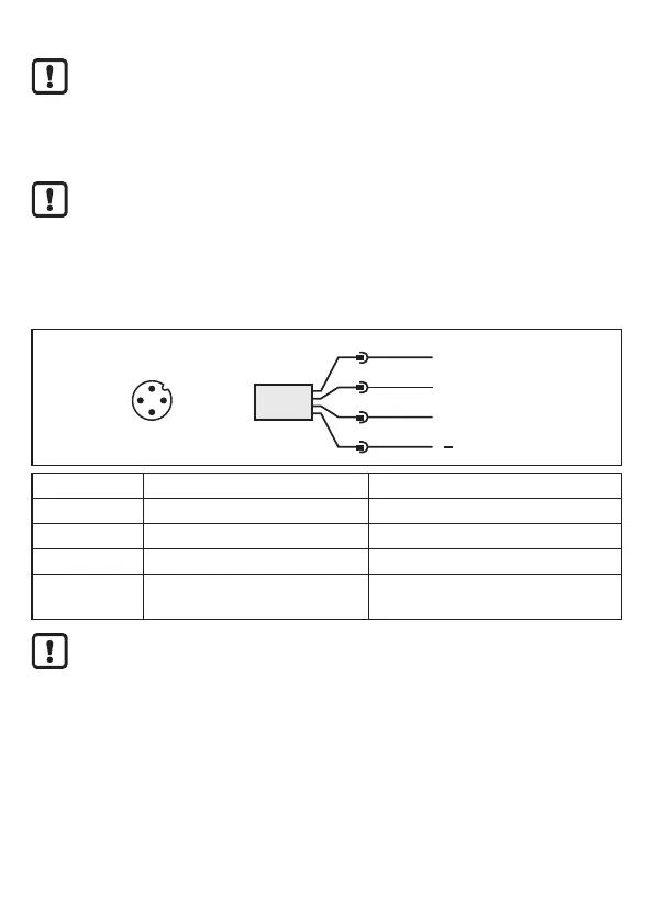
► Connect the unit as follows:
4
1
3
2
OUT2
L
+
L
OUT1/IO-Link
4
2
13
Pin Connection Core colours for ifm sockets
1 Ub+ brown
3 Ub- blue
2 (OUT2) pnp switching signal white
4 (OUT1)
• pnp switching signal
• IO-Link
black
When the unit is supplied with operating voltage for the first time, the
probe length, the medium to be detected and the type of probe used must
be entered� Only then is the unit ready for operation (→ 10.2)�