5
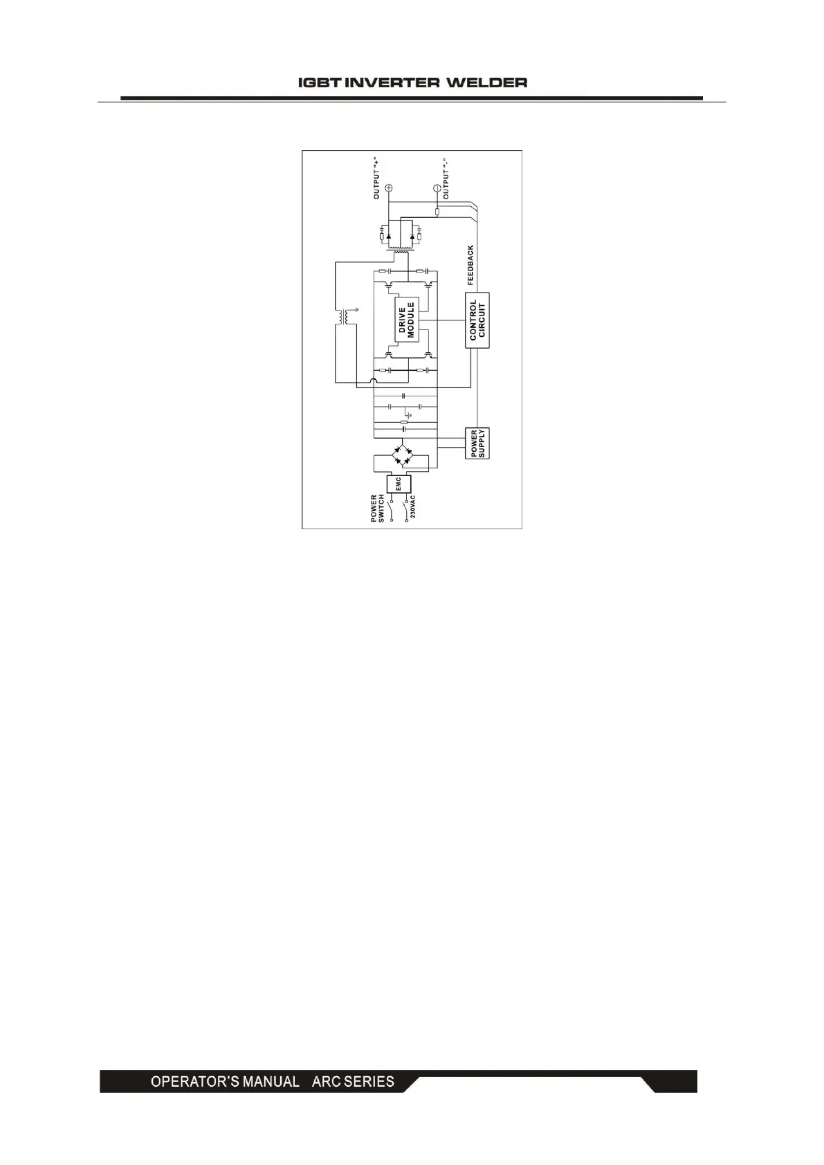
4. ELECTRIC BLOCK DIAGRAM
5. OPERATION CONTROL AND DESCRIPTION
● Front control panel (see Figure 1)
(1) "+" output terminal: To connect the electrode holder.
(2) "-" output terminal: To connect the work clamp.
(3) Welding current knob: To adjust the output current.
(4) Power LED: To indicate the power. Power LED on indicates that the power switch of the
machine is on.
(5) Overheating LED: To indicate overheating. Overheating LED on indicates that the
temperature inside the machine is too high and the machine is under overheating protection
status.
(6) MMA/TIG switch: To toggle between MMA and TIG.
● Back control panel (see Figure 2)
(7) Power input: Power input cable.
(8) Power switch: Power ON/OFF switch.
(9) Fan
 Loading...