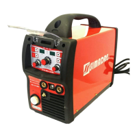
The MIG-200M is an IGBT Inverter Welder designed for multi-process welding applications, featuring an LCD display and MCU controller for enhanced user experience and efficiency.
Function Description:
The MIG-200M is a versatile welding machine capable of performing four different welding functions: Flux Cored Arc Welding, MIG Welding, TIG, and MMA (Manual Metal Arc) welding. It utilizes an inverter-based system with an MCU controller and a 4.2-inch TFT-LCD display, which simplifies parameter setting and improves overall welding efficiency. The machine incorporates a built-in welding expert database to enhance reliability by automatically setting welding parameters based on user selections. An optional MIG spool gun is available for aluminum welding.
Important Technical Specifications:
- Model: MIG-200M
- Input Voltage: 1ph 230V, 50Hz
- Welding Modes: MIG/FLUX, MMA, TIG
- Input Current (A): 34 (MIG/FLUX), 33 (MMA), 21 (TIG)
- Input Power (KVA): 7.5 (MIG/FLUX), 7.2 (MMA), 4.7 (TIG)
- No-load Voltage (V): 60 (all modes)
- Welding Current (A): 30~200 (MIG/FLUX), 20~175 (MMA), 20~175 (TIG)
- Welding Voltage (V): 15.5~24 (MIG/FLUX), 21~27 (MMA), 10.8~17 (TIG)
- Rated Duty Cycle: 35% (all modes, tested at 40°C by simulation)
- Welding Wire Diameter (mm): 0.6-1.0 (MIG/FLUX)
- Electrode Diameter (mm): 1.0-4.0 (MMA)
- Efficiency: 85%
- Power Factor: 0.7
- Protection Class: IP21S
- Insulation Class: F
- Minimum Power (Power Grid): 9.5 KVA
- Minimum Power (Generator): 12 KVA
- Input Protection (Fuse/MCB): 32 A
- PFC Version Note: The machine with PFC can operate under input voltages from 85V to 260V. Below 145V, it automatically switches to low voltage working mode, limiting output power. A restart is required to recover full output power after the input voltage exceeds 145V.
Usage Features:
The MIG-200M is designed for ease of use with its intuitive controls and display.
- Front Panel:
- Adjusting Knobs (1, 2): One knob for wire speed (MIG) or welding current (MMA/TIG), and another for welding voltage (MIG) or output on/off control (MMA/TIG).
- LCD (3): A 4.2-inch TFT-LCD for displaying welding techniques and parameters, offering high resolution and clear visibility.
- Home Button (4): Returns to the main menu for selecting welding techniques or display settings.
- Central Adjusting Knob (5): Rotates to select parameters and pushes to enter/confirm.
- Return Button (6): Returns to the previous menu.
- Welding Torch Connector (7): Ensures a tight and locked connection for the torch.
- Spool Gun Connector (8): For connecting the optional spool gun, typically used for aluminum welding.
- Welding Cable (9): Connects to "-" for Flux Cored welding and "+" for MIG welding.
- Output Connectors (10, 11): "-" and "+" terminals.
- Rear Panel:
- Gas Inlet (1): For connecting gas hoses.
- Power Switch (2): ON/OFF control.
- Fan (3): For cooling during operation.
- Internal Panel:
- Selector Switch (1): To choose the torch type for welding.
- Wire Spool Holder (2): To hold the welding wire.
- Wire Feeder (3): Feeds wire to the machine MIG torch; inactive in spool gun mode.
- Installation:
- Connects to a 1-phase 220V AC power supply with a leakage protection switch.
- Output cable connections vary by welding mode (MIG solid wire, Flux Cored, MMA).
- Spool gun usage requires selecting "Spool Gun" on the internal panel, using a 24V motor spool gun, AR 100% protection gas, and "SPOOL GUN ALUMINUM" welding mode.
- Filler Wire Threading: Detailed steps are provided for installing and threading 5 kg (200 mm) or 1 kg (100 mm) wire reels, adjusting pressure, and feeding the wire. A caution warns against pointing the gun at oneself or others due to the sharp wire end.
- Feed Roll Groove Change: Instructions for changing the feed roll groove for different wire diameters (0.6 mm vs. 0.8-1.0 mm).
- Shielding Gas: Connects to a gas bottle's control valve. Carbon dioxide or argon/carbon dioxide mixtures are used for steel wires. Flow rate (8-15 l/min) is adjusted via the control valve.
- Operation Steps:
- Power on the welder, open the gas bottle valve, and adjust gas pressure.
- Select torch type (if not using spool gun).
- Navigate the main menu using the central adjusting knob to select welding mode (e.g., MIG STEEL C25).
- Follow on-screen prompts for cable connections.
- Select welding wire diameter and material thickness.
- Manually fine-tune welding current (left knob) and voltage (right knob).
- Access advanced MIG settings (Run-in WFS, inductance, spot time) via the central adjusting knob.
- Options and Settings:
- MIG Options:
- Inductance: Adjusts arc performance, softer arc with higher inductance, crisper arc with lower.
- Spot Time: Adjusts welding arc duration for tack or spot welds (available in MIG and Flux Cored modes).
- Run-in: Adjusts wire feed speed before arc establishment for smooth starts (available in MIG and Flux Cored modes).
- MMA Options:
- Arc Force: Controls penetration profile (crisp arc with high value, soft arc with low value).
- Hot Start: Adjusts amperage during arc initialization.
- General Settings: Adjust display brightness, reset user interface software to factory settings, view software revision information, and select language (metric or English units).
- Available Equipment Options: Spool gun selection for aluminum welding, scratching TIG option, and foot pedal usage for TIG.
Maintenance Features:
The manual provides comprehensive guidelines for daily maintenance and troubleshooting to ensure the longevity and optimal performance of the welder.
- Safety Tips: Emphasizes the importance of ventilation (30cm minimum distance from objects), avoiding overload (observing duty cycle), preventing over-voltage, and allowing the fan to cool the machine after an overload without immediate restart.
- General Maintenance (requires professional knowledge):
- Periodically check inner circuit connections, tighten loose connections, and remove oxidization.
- Keep hands, hair, and tools away from moving parts like the fan.
- Clean dust periodically with dry, compressed air (daily in heavy smoke/pollution environments), ensuring proper air pressure to avoid damaging small parts.
- Avoid rain, water, and vapor; if present, dry the machine and check insulation.
- Check insulation covers of all cables and replace/rewrap if dilapidated.
- Store in original packing in a dry location when not in use for extended periods.
- Daily Maintenance:
- Remove welding spatters from the gun tip and check parts; replace damaged parts immediately.
- Check and replace damaged insulating tips of the welding gun's neck.
- Check tightness of welding gun's and earth cable's connections.
- Check condition of supply voltage and welding cables; replace faulty ones.
- Wire Feed Mechanism Maintenance:
- Service every time the reel is changed.
- Check wear of feed roll groove and replace if necessary.
- Clean welding gun wire guide with compressed air.
- Cleaning the Wire Guide:
- Remove gas nozzle, contact tip, and adapter.
- Blow compressed air through the wire guide with a pneumatic pistol.
- Blow the wire feed mechanism and reel housing clean.
- Changing the Wire Guide: Detailed instructions for disconnecting the welding gun, opening the mounting nut, withdrawing the old wire guide, inserting a new one, tightening, and cutting the new guide.
- Troubleshooting: A table lists common problems (e.g., LCD not lighting up, no wire feeding, unstable arc) and their potential causes (e.g., power switch off, broken wires, incorrect connections, overheating, gas issues, wrong settings), guiding users to identify and resolve issues.