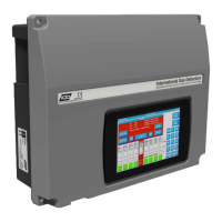
EasyManua.ls Logo

IGD TOC 635 PLUS - User Manual

IGD TOC 635 PLUS
34 pages
Print Icon
To Next Page IconTo Next Page
Loading...
SL-014 v1.6 Page1
Document Ref: SL-014 v1.6
TOC 635 PLUS
&
TOC 635 MICRO
A d d r e s s a b l e G a s D e t e c t o r C o n t r o l P a n e l
O p e r a t i o n , M a i n t e n a n c e a n d S a f e t y I n s t r u c t i o n M a n u a l
V 1 . 6
*Images for illustration only - see specification
within for dimensions and labelling
Addressable
2-Wire
Document Ref: SL-014 v1.6
Operation Manual
Control Panel
FS646773 EMS696504
Triton House
Crosby Street
Stockport
SK2 6SH
internationalgasdetectors.com
+44 (0)161 483 1415
sales@internationalgasdetectors.com
/international-gas-detectors-ltd
@

Questions and Answers

Summary

Brief Introduction

Main Features

Highlights key features of the 635 series control panels, including detector capacity and display.

Service & Maintenance Recommendations

Advises on recommended service intervals and training for control panels and detectors.

Safety and Performance Warnings

Outlines critical warnings regarding installation, environmental conditions, and system performance.

Basic Specification

Technical Specifications

Details power, construction, display, I/O, inputs, measurement ranges, and environmental ratings.

Model Feature Comparison

Compares key features and capabilities between TOC-635-PLUS and TOC-635-MICRO models.

Important Installation and Calibration Notes

Calibration Gas and Equipment Requirements

Specifies requirements for zero and calibration gases, traceability, and regulators.

General System Information

Physical Dimensions and Wiring

Provides physical dimensions, weight, and cabling considerations for the TOCSIN 635 series.

Installation Guidance and Training

IGD-Academy Training Resources

Information about IGD's online academy for training courses and videos on gas detection systems.

T635 PLUS PCB and I;O Details

T635 MICRO PCB and I;O Details

Details PCB features and I/O addresses for the TOCSIN 635 MICRO control panel.

Control Panel Interface and Display

Reading the Control Panel Display

Explains how to interpret the display readings, channel numbers, gas types, and alarm status.

WiFi Connectivity Features

Connecting and Using WiFi Module

Guides on connecting to the controller via WiFi for data download and setup editing.

Addressable Relay Card Configuration

Setting Relay Card Addresses

Explains how to set unique base addresses for addressable relay cards.

Addressable I;O Card Overview

2-Wire Highway Connections

Details the wiring connections for the 2-wire highway on the addressable I/O card.

Addressable I;O Card Input Ports

Input Port Configurations

Describes the types of inputs (digital/analogue) and their connections on the I/O card.

Special Status States and Indications

System Status Indicators

Lists system states, their on-screen indications, and corresponding relay states.

Day-to-Day Operation and User Actions

Display and Jog Wheel Usage

Explains how to navigate the display and use the jog wheel for normal operation.

Alarm and Fault Condition Handling

Describes user actions and display indications during alarm and fault conditions.

Controller Interface Components

Power Up Sequence and Indicators

Details the initial power-up sequence, LED indicators, and sounder functions.

Panel Navigation and Menu Access

Accessing User and Engineer Menus

Guides on entering menus using password and accessing specific menu sections like INHIBIT, USER, and ENGINEER.

TOC-635-PLUS Menu Structure

Engineer Menu Options

Details functions available under the Engineer Menu for setup and diagnostics.

User Menu Options

Details functions available under the User Menu for maintenance and calibration.

TOC-635-MICRO Menu Structure

Engineer Menu Options

Details functions available under the Engineer Menu for setup and diagnostics.

User Menu Options

Details functions available under the User Menu for maintenance and calibration.

Production Menu Overview

Production Menu Functions

Covers options for system reset, self-test, and navigation to user/engineer menus.

Putting Into Service

Initial Setup and Configuration Steps

Outlines the sequence for initial setup, including installation guide reference, sensor/relay FIND, and zeroing.

System Warm Up and Normal Operation

Warm Up Period Duration

Explains the warm-up period for detectors and system stabilization before normal operation.

Normal Operation Display

Describes how the system displays data from detectors during normal operation.

Putting into Service Checklist

Configuration and Setup Tasks

Lists key tasks for configuring the system, including adding devices, setting alarms, and zero/calibration.

New Setup Sequence

Discovering Devices (FIND Command)

Details the process of using the FIND command to discover and install connected devices.

Relay Output Testing

Explains how to test alarm relay outputs using the 'TEST RLY' function.

Bluetooth Controller Data Management

2-Wire Events App Usage

Guides on using the Events App to download, save, and view system events.

Controller Setup App Usage

Guides on using the Setup App to configure cause/effect, alarm levels, and tag lines.

Alarm Actions and Level Configuration

Alarm Type Selection

Explains the different alarm types (Rising Latching, Rising, Falling Latching, Falling) and their behaviour.

Alarm Level Presets

Default Alarm Level Settings

Presents default alarm levels for various gas types, referencing IGD document OIGD193.

Gas Detector Zeroing Procedure

Zeroing Process Steps

Details the step-by-step process for zeroing a gas detector via the controller menu.

Zero Gas Recommendations and Reaction Time

Recommended Zero Gases

Lists recommended zero gases for different detector types (O2/CO2, Pellistor, Toxic Gases).

Reaction Time Check

Describes how to check the detector's reaction time to calibration gas.

Gas Detector Calibration Function

Calibration Process Steps

Details the step-by-step process for calibrating a gas detector using calibration gas.

Modbus Interface for 635 PLUS

Modbus Communication Setup

Explains wiring and basic setup for Modbus RTU communication between the controller and a master.

Modbus Memory Map and Functions

Modbus Command Functions

Lists Modbus commands, their functions, registers, and returned data for sensor readings and control.

Troubleshooting Guide

System State Troubleshooting

Provides troubleshooting steps for various system states like Warm Up, Fault Communication, and Over Range.

Maintenance and Accessories

Offers recommendations for maintenance after exceeding measuring range and lists standard supplied accessories.

IGD TOC 635 PLUS Specifications

General IconGeneral
BrandIGD
ModelTOC 635 PLUS
CategoryControl Panel
LanguageEnglish

Related product manuals