EasyManua.ls Logo

IGD TOCSIN 750 Series User Manual

IGD TOCSIN 750 Series
64 pages
To Next Page IconTo Next Page
Page #1 background imageLoading...
Page #1 background image
1
TOC-750R-24
International Gas Detectors
Advanced Addressable Gas Detection System
ACCESS
KEY
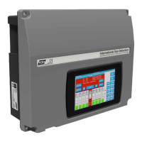
TOCSIN 750 SERIES
H M I B a s e d D e t e c t o r C o n t r o l P a n e l
O p e r a t i o n a n d M a i n t e n a n c e
V 3 . 6 1
Triton House
Crosby Street
Stockport
SK2 6SH
England
Tel: +44 (0)161 483 1415
Fax: +44 (0) 161 484 2345
Email: sales@internationalgasdetectors.co.uk
Website: www.internationalgasdetectors.co.uk
FS646773
REF: 750M-7
EMS696504

Questions and Answers:

IGD TOCSIN 750 Series Specifications

General IconGeneral
BrandIGD
ModelTOCSIN 750 Series
CategoryControl Panel
LanguageEnglish

Summary

Brief Introduction to Tocsin 750 Series

Key Features of Tocsin 750 and 650 Series

Service and Maintenance Recommendations

Warnings and Performance Statements

Basic Specification

Alternate Specifications for 19" Rack Version

Outlines alternative specifications for the 19" rack mounted 750R version.

EC Declaration of Conformity

System Example Diagram

Important Notes on Gas Detection Systems

Tocsin 750 Panel Options

General System Considerations

Tocsin 750 Physical Dimensions

Installation Guide Reference

T750 Control Panel PCB Features

Tocsin 750 Relay Card Address Setup

Tocsin 650/750 I/O Card Input Ports

Tocsin 750 Detector Node

Module PCB Interface Specifications

Lists the basic interface specifications for the detector node module PCB.

Interfacing to Remote Modbus Port

Modbus Command Structure

Details the command structure for Modbus communication with the controller.

Modbus Memory Map Functions

Operating System Overview

Special Status States

System Display During Alarm

Bar Graph Alarm Level Indicators

Describes the bar graph indicators for different alarm levels and their behavior.

System Display During Warm Up

System Display Inhibited for Service

System Display During Fault Detection

Required Setup Sequence

Engineer Menu and Functions

System Menu Access Levels

Operational Setup Philosophy

Sensor Setup Menu

Sensor FIND Function

Sensor Setup Tab Navigation

Shows how to navigate the sensor setup tab and its options.

Sensor Test Function

Sensor Test Function Results

Sensor Diagnostic Functions

Live Data Panel

Displays live readings and status information for a sensor channel.

Calibration Data Panel

Shows recorded zero and calibration data for a sensor.

Settings Data Panel

Displays configuration settings for a detected sensor.

Relay FIND Function

Relays Tab Navigation

Guides navigation through the Relays tab for setup and diagnostics.

Relay TEST Function

Relay Diagnostics Function

Relay Test Function Operation

Alarm Levels Menu

Alarms Tab Overview

Introduces the Alarms tab and its menu options for setting alarm levels.

Alarm Relay Setup Menu

Calibration Menu Options

Sensor ZERO Function

Sensor Zero Gas Recommendations

Sensor CALIBRATE Function

Connection Possibilities

750 Module Setup Functions

Accessing Module PCB Setup Functions

TOC-750 Module PCB Setup Overview

Pellistor Settings and Module Options

Details the setup options for Pellistor inputs, including address, range, and gas type.

T102 Settings and Module Options

I/O 1 and 2 Settings and Module Options

Explains setup for I/O ports 1 and 2, including input/output types and addresses.

Relay Settings and Module Options

Display Settings and Module Options

Covers display settings for detector nodes, including what information to show.

Annunciator Display Setup

Forcing a Channel Input

Backing Up Panel Setup Internally

Power Function Overview

Battery Care Recommendations

Offers recommendations for battery installation and maintenance for internal battery backups.

Modbus Settings Configuration

Modbus Diagnostics

GSM Module Functions Overview

GSM Mobile Provider Settings

GSM Contacts and Alarms Setup

GSM Gas Values and Events Reports

GSM System Status and Remote Control

GSM Module Test Functions

Information on 19" Rack Versions

Tocsin 750R System Controller Layout

Illustrates the layout and features of the Tocsin 750R system controller rack version.

Tocsin 750R Input-Output Rack

Tocsin 750R Rear Panel Connections

TOC-750R-24 Port Locations

Identifies the locations of various ports on the TOC-750R-24 rear panel.

Tocsin 750R I-O Rack Rear Panel Connections

TOC-750R-IO Ports Location

Identifies the locations of various ports on the TOC-750R-IO rack unit's rear panel.

Tocsin 750R Rack Connector Pin Outs

Relay Output Connector Pin Out

Details the pin configuration for relay output connectors.

Digital Input Connector Pin Out

Details the pin configuration for digital input connectors.

4-20mA Input Connector Pin Out

Details the pin configuration for 4-20mA input connectors.

Highway Connection Pin Out

Details the pin configuration for highway connection connectors.

HMI Connection Pin Out

Details the pin configuration for the HMI connection on the controller.

Troubleshooting Common Faults

Available Accessories

Related product manuals