14
B
A
0V DC
Screen
B
A
0V DC
RS485 Modbus
Comms Port
RS485 Modbus
Comms Port
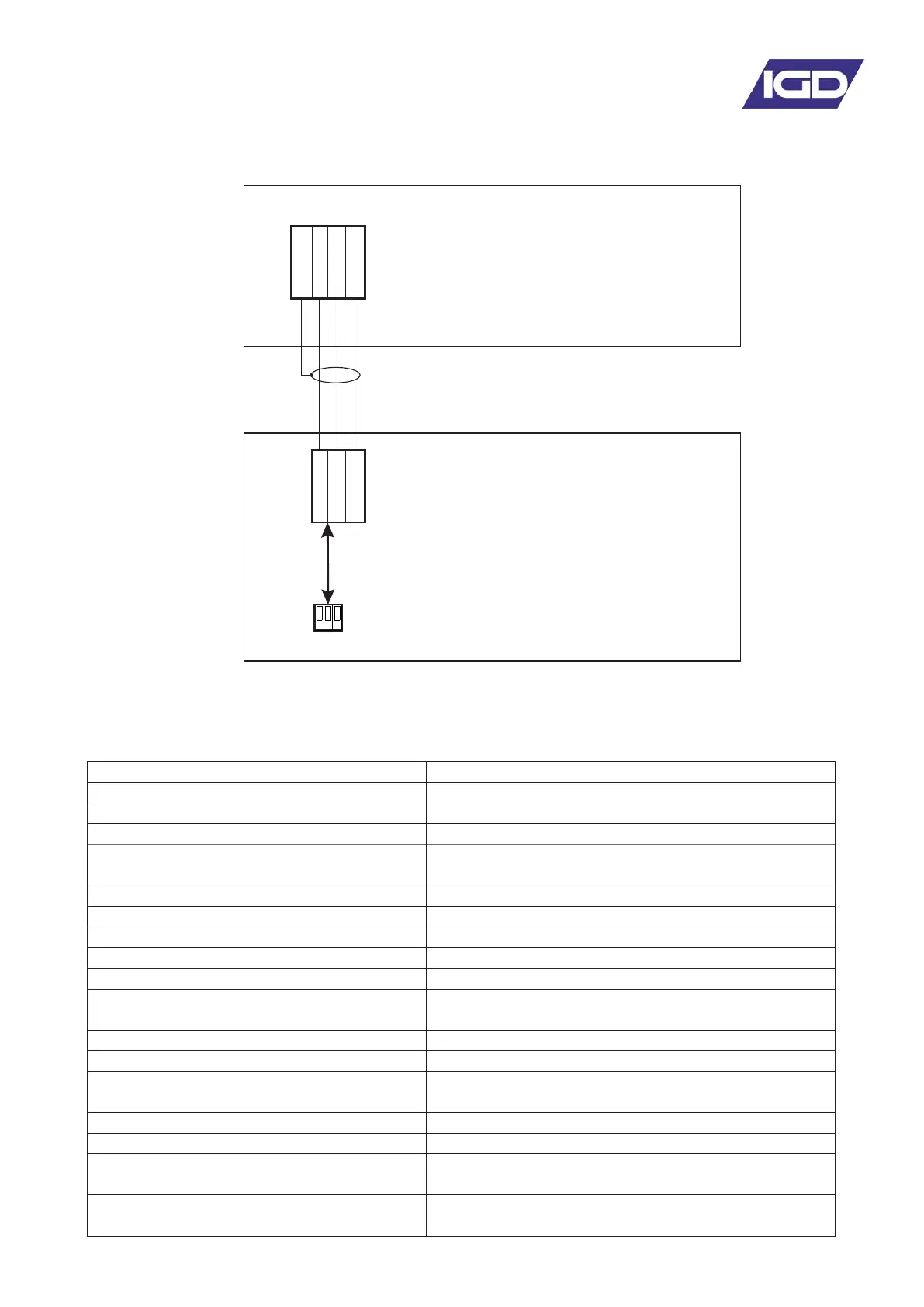
Interfacing to the Remote Modbus Port
Tocsin 650/750 Controller (slave)
Master DCS/BMS
Note only the A,B and 0V DC Connections are
Used. 0V DC between master and slave should
be connected for correct operation and to prevent
damage to both master and slave systems
The Tocsin 640 controller has an in-built memory map allowing access to alarm status, panel status,
readings etc using Modbus RTU protocol. Wiring between units is as follows:
MODBUS INTERNAL MEMORY MAP ADDRESSES
COMMAND STRUCTURE
Maximum = 100mS
(5s for Zero Command)
4800, 9600, 19200 (19200=default)
None, Odd, Even
(Odd=default. None=T700 only)
1, 2 (1=default & T700 only)
2 Wire RS232, 2 Wire RS485
(2 Wire RS485=Optional on T900)
Least significant bit transmitted first
Least significant byte transmitted first
Maximum = 1.5 bytes times
(781uS @ 19200 Baud)
Minimum = 3.5 bytes times
(1823uS @ 19200 Baud)