6
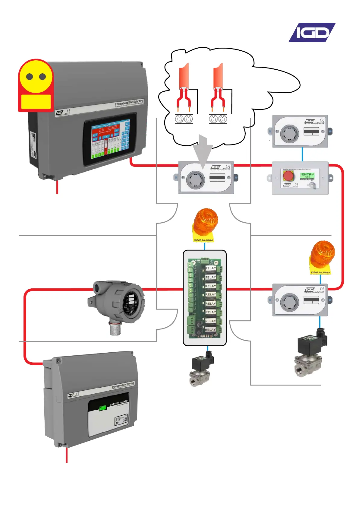
System Example
LPG
0-100%LEL
SN:20235-1-1 ADD:4110
GAS DETECTOR
LPG
0-100%LEL
SN:20235-1-1 ADD:4110
GAS DETECTOR
LPG
0-100%LEL
SN:20235-1-1 ADD:4110
GAS DETECTOR
Controller in Supervisors Office
ATEX Zoned Area
Laboratory
Gas Bottle Store
Addressable
2-Wire
Mains Power
Mains Power
Power Booster
L1L1
L2L2
E
E
OUTIN
Screen or Drain Wire
Cable Highway
Note 2
Note 1
Note 3
Note 4
Note 7
Note 8
Note 6
Note 5
1 Controllers can have internal or external battery backup
2 System devices connect using 2 core cable, there is no
polarity requirement for the ‘highway cabling.
3 Use room status indicators to protect entry ways, these
can display selected detector values for the area
4 Both ATEX/IECEX rated and safe area devices are available
5 Detector nodes have I/O capability and can directly run
beacon sounders or input other 4-20mA signals
6 Use the built in detector node relays to control external
devices such as gas valves
7 Power modules are available for larger systems
8 Fit i/o cards on the same highway where control is required