41
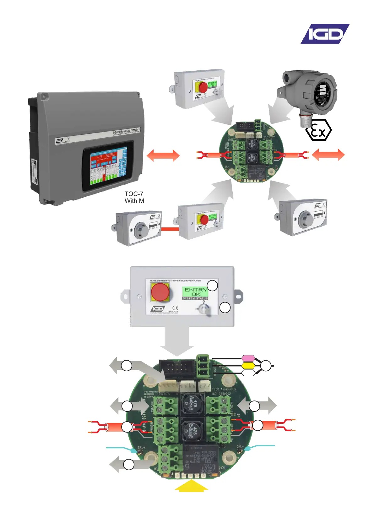
750 Module Setup Functions
The Tocsin 750 system uses a common module PCB to connect and interface detector and
other input/outputs. The 750 control panel has built in routines to access and setup the
module PCB. The following Diagram shows some of the connection possibilities.
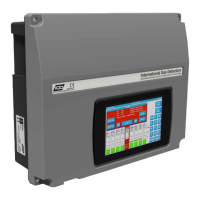
TOC-750 Annunciator
TOC-750 Annunciator
With MK7 Gas Detector
TOC-750 Series
Safe Area
Gas Detector
TOC-750 ATEX Hazardous Area
Gas Detector
2 Core Cable Highway For
Power and Communication
Between Module PCB’s
and Control Panel
The following diagram indicates features available on the TOC-750 ‘module’ PCB. Please note that failure
to observe and make correct connections or exceed ratings may result in damage to the PCB.
Ribbon Cable Connection For TOC-750
Annunciator Display and Options
Local LED Indications
And Up/Down Interface Buttons
Pellistor (Catalytic)
Flammable Gas
Detector Interface
Suitable for IGD
Types MK3, MK6, MK7
2-Wire Highway
Connection
To Next Device
Multi-Function I/O Port 1
Solid State Output or
4-20mA Input or
TOC-10 IP or Gas Meter
Multi-Function I/O Port 2
Solid State Output or
4-20mA Input or
TOC-10 IP or Gas Meter
Connection Point For
IGD Infra-Red, Toxic, PID
or Oxygen Gas Detectors
2-Wire Highway
Connection
To Next Device
P
Y
W
SPCO Relay
Output
DVM Test Point +
DVM Test Point -
2
7
5
6
4
3 3
1
1