6
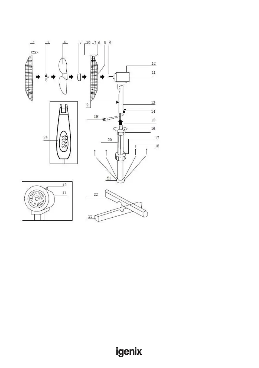
APPLIANCE OVERVIEW
ASSEMBLY INSTRUCTIONS
Before Assembling
• Check that you have all of the component parts following the content list
(g 1) and familiarise yourself with each part before proceeding.
• Ensure you have enough space to lay out all the parts before assembly.
• Take all the parts out of the plastic bag and separate them into their groups.
• To avoid scratching, it is recommended that you assemble the appliance on a
soft level surface
Fig 1:
1. Front Guard
2. Locking Screw
3. Blade Cap
4. Fan Blade
5. Locking Nut
6. Handle
7. Rear Guard
8. Holes Motor Spindle
9. Motor Spindle
10. Clips
11. Motor
12. Oscillation Control
13. Fan Control Box
14. Set Screw
15. Inner Pipe
16. Collar (for tube height adjustment)
17. Base Cap
18. Bolts (4 pcs)
19. Mains Cord
20. Stand Pipe
21. Flange
22. Upper Cross-Bar Base
23. Lower Cross-Bar Base
24. Speed Control Button