EasyManua.ls Logo

Igloo EWA 500.P - User Manual

Igloo EWA 500.P
48 pages
Go to English
Print Icon
To Next Page IconTo Next Page
Loading...
1
pl
Instrukcja obsługi Szafy chłodnicze, średnio-mroźnicze i mroźniczewww.igloo.pl
Spis treści Spis rysunków
Spis tabel
Rys.1 Budowa urządzenia 2
Rys.2 Usuwanie podestu drewnianego 4
Rys.3 Mocowanie uchwytu drzwi 4
Rys.4 Mocowanie półek perforowanych 4
Rys.5 Tacka na skropliny (widok od tyłu urządzenia) 5
Rys.6 Pojemnik na skropliny (widok od przodu urządzenia) 5
Rys.7 Panel sterowania 5
Rys.8 Czujnik temperatury wewnątrz szafy 7
Rys.9 Czyszczenie skraplacza 7
Rys.10 Wymiana świetlówki wewnątrz szafy 8
Rys.11 Wymiana świetlówki panelu górnego 8
Rys.12 Tabliczka znamionowa 10
Rys.13 Panel termostatu „Igloo” 11
Rys.14 Panel termostatu „Carel” 12
1. ROZŁADUNEK 1
2. CHARAKTERYSTYKA WYROBU 1
2.1. Przeznaczenie 1
2.2. Opis urządzenia 1
2.3. Dane techniczne 3
3. PRZYGOTOWANIE URZĄDZENIA DO EKSPLOATACJI 4
3.1. Wymagania dotyczące miejsca instalacji 4
3.2. Podłączenie i uruchomienie 4
4. EKSPLOATACJA 6
4.1. Regulacja temperatury 6
5. KONSERWACJA 7
5.1. Czyszczenie i konserwacja 7
6. SERWIS 9
6.1. Identy kacja i naprawa usterek 9
6.2. Serwis 10
7. OBSŁUGA TERMOSTATU 11
7.1. Termostat „IGLOO” 11
7.2. Termostat „CAREL” 12
Tabela 1 SZAFA TYPU „EWA”* 3
Tabela 2 SZAFA TYPU „JOLA”* 3
Tabela 3 SZAFA TYPU „OLA”* - cz.1 3
Tabela 4 SZAFA TYPU „OLA”* - cz.2 3
Tabela 5 SZAFA TYPU „OLA 2” 3
1. ROZŁADUNEK
Urządzenie powinno być transportowane w pozycji pionowej, odpowiednio zabezpieczone i spakowane. Producent wysy-
ła urządzenie na specjalnym podeście drewnianym, zabezpieczone tekturowymi kątownikami oraz folią.
2. CHARAKTERYSTYKA WYROBU
2.1. Przeznaczenie
Szafy produkowane przez rmę „Igloo” należą do profesjonalnych urządzeń chłodniczych i mroźniczych. Przeznaczone
są do krótkoterminowego przechowywania artykułów spożywczych. Mają zastosowanie w zakładach gastronomicznych,
cukierniach, kawiarniach i sieciach sklepów. Przechowywanie produktów spożywczych w stanie schłodzonym pozwa-
la na zachowanie ich walorów smakowych, zapachowych i estetycznych. Gwarantowane temperatury wewnątrz szaf:
chłodniczych +2ºC/+8ºC; średnio-mroźniczych (SM) -6ºC/-2ºC i mroźniczych (M) -18ºC/-12ºC przy temperaturze otocze-
nia +15ºC/+25ºC i wilgotności wzgl. powietrza do 60%.
2.2. Opis urządzenia
Szafy wyposażone są w agregat wewnętrzny, umieszczony w dolnej części urządzania. Chłodzenie odbywa się na za-
sadzie wymuszonego obiegu powietrza. Wszystkie szafy wyposażone są w odszranianie automatyczne i elektroniczny
termostat opcjonalnie współpracujący z modułem do rejestracji temperatury pozwalającym na rejestrację i sygnalizację
za wysokiej i za niskiej temperatury w urządzeniu. W zależności od opcji mogą posiadać automatyczne odparowanie
kondensatu. W zależności od typu szafy dzielimy je na pełne, bądź przeszklone. Szafy wyposażone są w 5 rzędów
łek siatkowych z regulacją wysokości położenia. Urządzenia „IGLOO” wykonywane są w/g nowoczesnych technologii
i posiadają wymagane prawem certy katy.
Tym znakiem oznaczone są informacje o szczególnym znaczeniu dla bezpieczeństwa użytkownika
oraz do prawidłowej eksploatacji urządzenia
Instrukcja obsługi
SZAFY CHŁODNICZE,
ŚREDNIO-MROŹNICZE
I MROŹNICZE
pl

Table of Contents

Question and Answer IconNeed help?

Do you have a question about the Igloo EWA 500.P and is the answer not in the manual?

Overview

This document describes the Igloo brand of medium-freezing and freezing cabinets, designed for professional use in various commercial settings.

Function Description

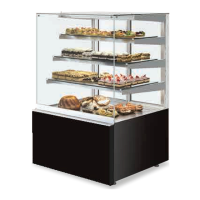
These cabinets are intended for the short-term storage of food products, helping to maintain their taste, smell, and aesthetic qualities. They are suitable for use in gastronomy establishments, confectioneries, coffee houses, and retail chains.

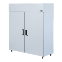
The cabinets are equipped with an internal cooling aggregate located in the lower part of the device. Cooling is achieved through forced air circulation. All cabinets feature automatic defrosting and an electronic thermostat. Optionally, the thermostat can cooperate with a temperature recording module to log and signal excessively low or high temperatures. Depending on the specific model, some units may also include automatic condensate evaporation.

The cabinets are available in full (solid door) or glazed (glass door) versions. They come with five rows of net shelves, whose height can be adjusted to accommodate different product sizes. The devices are manufactured using modern technologies and comply with all required legal certifications.

Important Technical Specifications

The manual provides detailed technical specifications across several tables for different cabinet types: "EWA", "JOLA", and "OLA".

Common Specifications:

  • Power Supply: All models operate on a 230V/50Hz power supply.
  • Maximal Load of 1 Shelf: Each shelf can support a maximum load of 30 kg across all models.

"EWA" Display Cabinets (Table 1):

  • Models: 500.P, 500.1, 500.2, 500.P M, 500.1 M.
  • Rated Current [A]: Ranges from 1.5 A (500.P) to 2.6 A (500.1 M).
  • Rated Lighting Power [W]: 51 W for 500.P and 500.P M; 66 W for 500.1 and 500.2.
  • Electric Energy Consumption [kWh/24h]: Ranges from 4.2 kWh/24h (500.P) to 8.0 kWh/24h (500.1 M).
  • Usable Volume [dm³]: 500 dm³ for all "EWA" models.
  • Number of Shelves [items]: 5 for all "EWA" models.
  • Shelf Dimension [mm]: 470 x 510 for all "EWA" models.

"JOLA" Display Cabinets (Table 2):

  • Models: 700.P, 700.1, 700.2, 700.P SM, 700.P M, 700.1 M.
  • Rated Current [A]: Ranges from 1.9 A (700.P) to 3.2 A (700.1 M).
  • Rated Lighting Power [W]: 54 W for 700.P, 700.P SM, 700.P M, 700.1 M; 72 W for 700.1 and 700.2.
  • Electric Energy Consumption [kWh/24h]: Ranges from 5.3 kWh/24h (700.P) to 9.8 kWh/24h (700.1 M).
  • Usable Volume [dm³]: 700 dm³ for all "JOLA" models.
  • Number of Shelves [items]: 5 for all "JOLA" models.
  • Shelf Dimension [mm]: 710 x 510 for all "JOLA" models.

"OLA" Display Cabinets (Table 3 & 4):

  • Models: 1400.P, 1400.PS, 1400.2, 1400.2S, 1400.4, 1400.4S, 1400.P SM, 1400.P M, 1400.2 M.
  • Rated Current [A]: Ranges from 2.6 A (1400.P, 1400.PS) to 4.1 A (1400.2 M).
  • Rated Lighting Power [W]: 94 W for 1400.P, 1400.PS, 1400.2, 1400.2S, 1400.4, 1400.4S; 7.2 W for 1400.P M, 1400.2 M.
  • Electric Energy Consumption [kWh/24h]: Ranges from 8.1 kWh/24h (1400.P, 1400.PS) to 12.2 kWh/24h (1400.2 M).
  • Usable Volume [dm³]: 1400 dm³ for all "OLA" models.
  • Number of Shelves [items]: 10 for all "OLA" models.
  • Shelf Dimension [mm]: 710 x 510 for all "OLA" models.

"OLA 2" Display Cabinets (Table 5):

  • Models: 2/1400.P, 2/1400.2, 2/1400.2 S.
  • Rated Current [A]: Ranges from 2.9 A (2/1400.P) to 3.3 A (2/1400.2, 2/1400.2 S).
  • Rated Lighting Power [W]: 72 W for 2/1400.2 and 2/1400.2 S.
  • Electric Energy Consumption [kWh/24h]: Ranges from 8.1 kWh/24h (2/1400.P) to 9.0 kWh/24h (2/1400.2, 2/1400.2 S).
  • Usable Volume [dm³]: 1400 dm³ for all "OLA 2" models.
  • Number of Shelves [items]: 10** for all "OLA 2" models. (Note: OLA 2 cabinets have net shelves as standard, but can accommodate a frame for GN containers).
  • Shelf Dimension [mm]: 530 x 650 for all "OLA 2" models.

Cabinets with interiors made of galvanized steel sheet covered with polyester are designated with a "B" in their name; their data is identical to the tables above.

Usage Features

Installation:

  • The device should be transported vertically, properly secured and packed.
  • Upon delivery, remove the wooden platform and level the device using its adjustable feet.
  • Ensure the power supply cables have an adequate cross-section for the device's power consumption.
  • Crucially, do not connect the device using extension cords or multi-sockets. It must be connected to a separate, properly installed electrical circuit with a protective earth pin, in accordance with applicable electrical equipment construction regulations.
  • The device can only be operated after confirming the effectiveness of fire protection through measurements compliant with current regulations.
  • If the device is partially disassembled for transport, reassemble components like door grips and shelves as per the instructions.
  • For "Ewa" and "Jola" type cabinets, the condensate tray needs to be placed directly under the cabinet at the back due to limited space around the aggregate. For "Ola" and "Ola 2" types, the condensate container is placed at the front.
  • After installation, allow the device to rest for at least 2 hours before turning it on to allow the refrigerant level to stabilize, preventing compressor startup issues.
  • The first cleaning should be done after unpacking and before turning on the device, using water not exceeding 40°C and a neutral detergent. Avoid using chlorine or sodium-based cleaning agents as they can damage the protective layer and components.
  • Do not use a water jet for cleaning; use a damp cloth.
  • Connect the power plug directly to the wall socket.
  • Turn on the main switch to activate the temperature regulator and the cooling aggregate.
  • Set the desired temperature on the thermostat panel.
  • Turn on the internal and panel lighting using the dedicated switch.

Operation:

  • The temperature inside the cooled space and the aggregate's operating cycle can fluctuate based on ambient temperature and the quantity/temperature of products stored.
  • Avoid unnecessary door openings.
  • Place the device in a dry, shaded, well-ventilated area with at least 10 cm clearance from walls, away from heat sources and air-circulating devices (e.g., ceiling fans, portable heaters).
  • The device operates correctly within the climate class specified on the data plate (typically +15°C to +25°C ambient temperature with up to 60% relative humidity). Performance may degrade outside this range.
  • Important:
    • Allow 2 hours after transport before starting the unit.
    • Fill the freezing compartment only after it has reached its working temperature.
    • Do not place hot products in cooling or freezing devices.
    • Do not store bottles or cans with drinks in freezing devices, as expansion during freezing can rupture them, posing a risk of injury and damage.
    • Do not exceed the daily freezing capacity of the device.
    • Do not overfill shelves; ensure even load distribution and do not exceed the maximum load.
    • Dry packages thoroughly before placing them in the device to prevent freezing.
    • Do not block any ventilation openings to ensure proper air circulation. This includes aggregate ventilation openings.
    • Keep the condenser clean to prevent compressor overheating and damage, which is not covered by warranty.
    • Do not use electrical devices inside the food storage chamber.
    • After closing the doors, do not force them open; the internal pressure equalizes within 1-2 minutes, allowing for easy opening.
    • Avoid leaving doors open for extended periods.

Temperature Regulation:

  • The thermostat controls the cooling aggregate to maintain the set temperature. Factory settings are pre-programmed. Users should verify and adjust the desired temperature on the control panel before first use.
  • The digital display shows the current internal temperature.
  • Warning: Do not interfere with the thermostat's system parameters, as this voids the warranty and can lead to serious damage.
  • "Igloo" Thermostat (Fig. 13):
    • Checking Set Temperature: Press "▲" or "▼" once. The set temperature will appear on the display with a red blinking dot. The display returns to normal after 3 seconds.
    • Adjusting Temperature: Press "▼" (or "▲") to see the set temperature, then press "▼" to decrease (or "▲" to increase) to the desired value. The display returns to normal after 3 seconds.
    • Manual Defrosting: Press button 2. This initiates a defrosting cycle regardless of automatic defrosting. It will not work if the temperature is higher than the defrosting end temperature.
    • Recommendation: Use the main switch to turn the aggregate on/off, not the thermostat's direct switch. The main switch automatically activates the thermostat.
  • "Carel" Thermostat (Fig. 14):
    • Display Diodes:
      • Diode 1 (Compressor): On when compressor is working; blinks for delayed start or continuous working mode.
      • Diode 2 (Ventilator): On when evaporator ventilators are on; blinks for delayed start.
      • Diode 3 (Defrosting): On when defrosting is active; blinks for delayed start.
      • Diode 4 (Alarm): On when an alarm is active.
      • Diode 5: Displays current internal temperature (with decimal places).
    • Setting Desired Temperature: Press "SET" for 1 second. The leading value appears. Use "▲" and "▼" to adjust. Press "SET" again to confirm.
    • Manual Defrosting: Press and hold the defrosting switch for at least 5 seconds. Diode 1 will blink during manual defrosting.
    • Warning: Failure to follow connection and operation rules in this manual may result in warranty voidance.

Troubleshooting (Fault Identification and Repair):

  • Device not working: Check power connection, voltage/frequency, main switch, and thermostat activation (if "Igloo" thermostat shows two dots, turn it on).
  • Water leakage: Verify leveling, clear outlet hoses, and empty condensate tray/container.
  • Lighting not working: Check lighting switch and fluorescent lamp/starter.
  • Device not reaching proper temperature: Check main switch, thermostat settings, thermostat function, condenser cleanliness, ambient temperature (should not exceed 25°C), sufficient cooling time for products, overfilling, door seal, and ventilation holes.
  • Thermostat error codes:
    • "Igloo" (CO, C1, C2): Indicates damaged temperature sensors. Call authorized service.
    • "Carel" (E0, E1, L0, HI, EE, Ed, DF): Indicates sensor failures, temperature alarms, internal regulator defects, or defrosting issues. Call authorized service for E0, E1, L0, HI, EE. Ed and DF are not alarm signals.
  • Device working, sound signaling activated ("Igloo"): Check condenser cleanliness, condenser fan operation, and ambient temperature (should not exceed 25°C).
  • Device too loud: Verify stable and level placement, ensure adjacent furniture does not vibrate, and internal elements are properly mounted.
  • Noise during operation: Normal phenomenon due to fans, motors, and compressors turning on/off, and refrigerant flow. This is a technical characteristic, not a defect.
  • Steam precipitation on glass: Natural phenomenon if relative air humidity exceeds 60%; does not require service.

Maintenance Features

General Maintenance:

  • Always disconnect the device from power before any maintenance.
  • Protect electrical installations from damage or water.
  • Do not use a water jet for cleaning; use a damp cloth.
  • Do not use sharp objects to remove dirt.
  • Do not damage the temperature sensor (Fig. 8) during operation or maintenance.
  • Monthly: It is recommended to take the device out of operation to clean its interior, defrost the evaporator, clean the condenser, and check door seal condition.
  • Do not use mechanical means to accelerate defrosting.

Condenser Cleaning (Fig. 9):

  • Keep the condenser clean. Dirt hinders heat exchange, increases energy consumption, and can damage the compressor.
  • To clean, pull out the wind brace by lifting it from its catches.
  • Clean condenser lamellas with a soft brush or paintbrush.
  • For heavily soiled (blocked) lamellas, use a vacuum cleaner or compressed nitrogen to suck/blow dirt from between them.
  • The manufacturer is not responsible for damages to the condenser aggregate resulting from non-observance of cleanliness.

Condensate Removal:

  • If the device does not have automatic condensate evaporation, remove condensate from the tray (Fig. 5) or container (Fig. 6) when it fills up. The frequency depends on operating conditions (air humidity, door opening frequency, etc.).

Door Seal Maintenance:

  • Clean door seals with clean water only, without detergents, and dry them thoroughly.
  • The seal must not come into contact with greasy substances or oils.
  • During maintenance, check if the doors close properly.
  • Test: Place a sheet of paper between the seal and the casing, close the door, and try to pull the paper out. It should offer noticeable resistance.

Fluorescent Lamp Replacement:

  • Internal Lamp (Fig. 10):
    1. Remove the transparent casing (5).
    2. Remove the fluorescent lamp (4) and starter (1).
    3. Replace with new components.
    4. Reattach the casing.
  • Upper Panel Lamp (Fig. 11):
    1. Remove the Plexi plate of the upper panel (1) by releasing the grips (2).
    2. Unscrew the metal screw (5) holding the lamp grip (3).
    3. Remove the fluorescent lamp (4) and starter (8) from their casings (7, 9).
    4. Replace with new components.
    5. Reassemble in reverse order.
  • Warning: During maintenance, be careful not to damage the data plate (Fig. 12), as it contains important information for service and waste disposal.

Service Contact:

  • IGLOO service telephone: +48 (14) 662 19 56 or +48 605 606 071.
  • Email: serwis@igloo.pl
  • When contacting service, provide the serial number (NS), production date, device type, purchase date, problem description, and your full address and phone number (with area code) from the data plate.

Igloo EWA 500.P Specifications

General IconGeneral
BrandIgloo
ModelEWA 500.P
CategoryDisplay Case
LanguageEnglish

Related product manuals