COMCO IKARUS
Maintenance Manual C42 Series
MaintenanceManual C42-
Series_Issue_VII_18.02.2014.doc
Revison No.:1 95 from 107
6.2.3 Control surface deflections
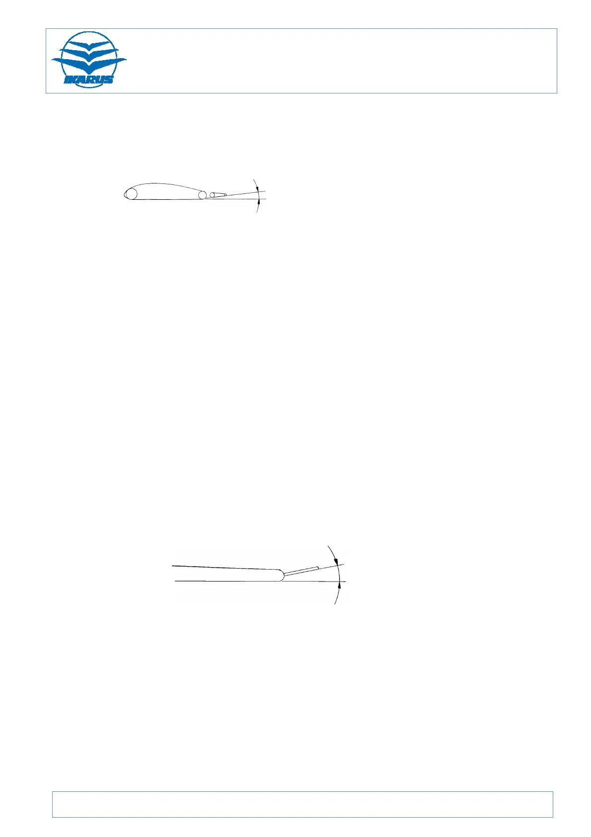
Note: The basic setting of the ailerons is 7° relative to airfoil chord (tangent front to
rear spar). It is defined by the length of the aileron push-rods.
-7° distance from axis of rotation
Aileron
up 20° 85 mm, + 10 mm 250 mm
down 14° 60 mm, + 10 mm 250 mm
Elevator
up 28° 200 mm, ± 15 mm 410 mm
down 20° 140 mm, ± 15 mm 410 mm
Rudder
to the right 32° 225 mm, ± 10 mm 410 mm
to the left 32° 225 mm, ± 10 mm 410 mm
Wing flaps
Note: The angle measured is the angle between wing flap underside and wing
underside at the wing root (tangent front to rear spar).
1st notch (cruise) -5° 27 mm, ±15 mm 310 mm
2nd notch (take-off/landing) 11° 60 mm, ± 15 mm 310 mm
3rd notch (landing) 32° 170 mm, ± 15 mm 310 mm
Trim tab
Lever nose-heavy: trim tab to elevator surface -5°
-5°
6.2.4 Tyre pressure
Main landing gear 2,0 – 2,5 bar 29 – 36 PSI
Nose wheel landing gear 1,6 – 2,0 bar 23 – 29 PSI
 Loading...