(j) SYNC SEPARATION
Separation circuit which se]eds between the internal sync included
in lhe video signal and extema1 sync of Lhe HDND composj(e signal,
and separates lhe mixed signal inlo HD and VD.
As the internal sync sigaal, the Y sigaals (YPbPr/RGB) and Y sigaal
Y/C separated from the composite sigaal are selected with the IC9!6
analog switch.
The inlemal and external sync signals a.re se1eded by IC901.
The cornposile sync signal is separated into the HD, VD, and back
porch sigaals by IC902.
The sync sigaals from the HDIV and SDIV SD!s are supplied as
the HD and VD sigaal&
Therefore the HD and VD sigaals separated by IC902 are selected
by IC906 and IC907.
A simple low pass filler delects the presence of the HD and VD sig-
nals. When no signal, lhe information is conveyed lo the MPU
BOARD and the MPU side is self-oscillation.
(k) SYNC PROCESS
Cirrui~ which processes the width and phase of the delay (!IN),
clarop (II), and blanking (!IN) pulses of each fo1TI1at based on the
control from the MPU.
Counling the clock generated from HD creates each pulse.
(I) BLK
Cirruit, which generales the BLK signal required for the CRT Gl
electrode, and bias pulse required for the beam feedback.
The BLK created from the deflection block FBP and V. BLK created
from the VD become the BLK sigaal in IC911, and is switched by
TR905.
The bias pulse for the 3H afler V. Bl.K ends is created inside IC911,
and is switched by TR906.
The BLK signal and bias pulse are mixed, and output from the
1R907 emitter follower circuit to drive the CRT Gl via lhe RGB
OUTBOARD.
(m)PLL/VCO
In IC912, comparing the phase of the pu]se that counted down from
lID and clock, lo generale lhe clock required for the counting ofIC
for SYNCPROCESS by VCO.
(n) SERI/PARA
In IC9!0 and IC915, the serial data from the MPU BOARD is con-
verled lo parallel control signal lo contro] each format and function.
- 18 -
(3) Adjustment procedure
* Unless slated, input the HDIV color bar (100%)/SDIV color
bar (75%) and set each control item into the preset slate.
(a) VR101: R-YLEVEL
VRJOI: Y IBVEL
VRSOl: B-YIBVEL
CD Input the HDIV color bar using the RGB sigaal, and set the AUX
input format 10 the RGB mode.
@ At the lest points 1P!Ol (Pr), 1P301 (Y) and 1P501 (Pb), adjust
the Y, Pb and Pr leve]s converted from the RGB 10 lhe same level as
Iha! in the Y, Pb and Pr mode using the Y,Pb and Pr inputs.
® Even when inputting the SDIV color bar with the RGB sigaal,
check that the leve] of each signal is the same.
(b) VR106:R-YOFFSET
VR506: B-YOFF SET
CD Input the HDIV grayscale sigaal (monochrome video), and set the
AUX input format lo the ROB mode.
@ Minimize the leaked video sigaals at the 1P!Ol (Pr) and 1P50!
(Pb) lest points.
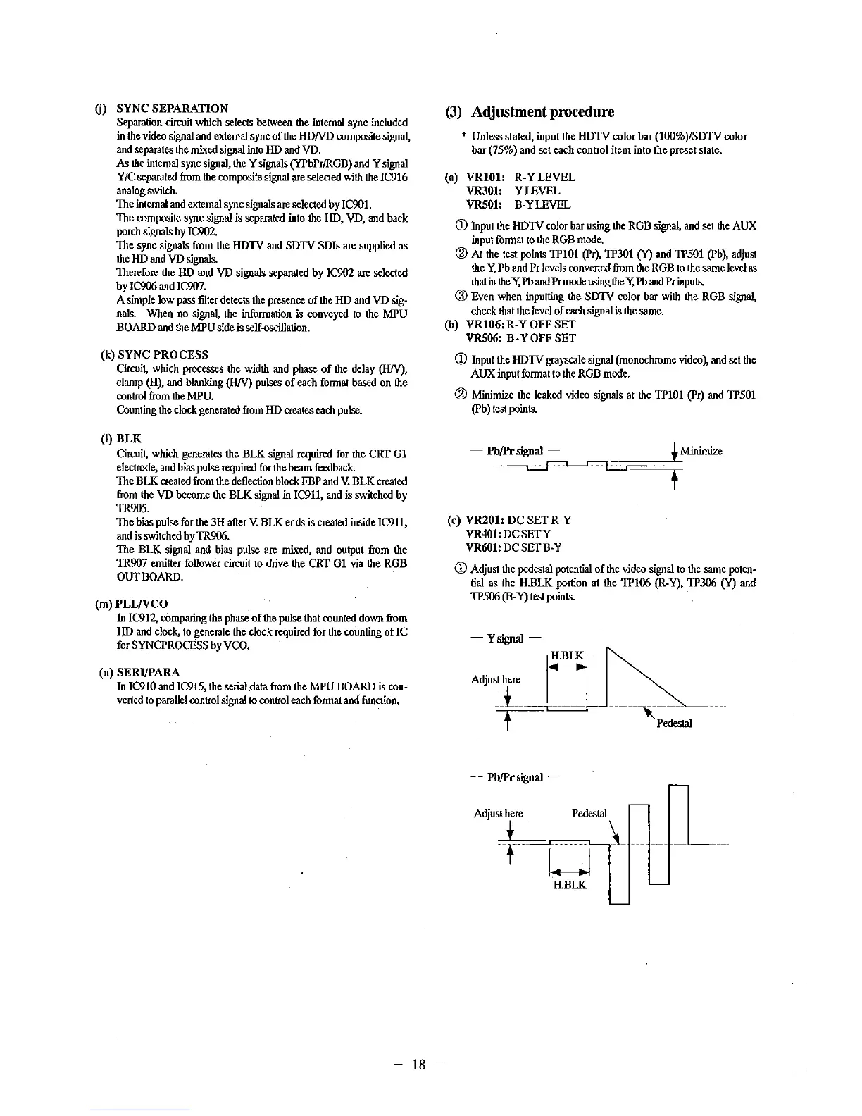
- Pb/Prsignal - !Minimize
--~----
(c) VR201: DCSETR-Y
VR401: DCSEIY
VR601: DCSEIB-Y
t
CD Adjust the pedestal potential of the video sigaal lo the same poten-
tial as the H.BLK portion at the 1P106 (R-Y), 1P306 (Y) and
1P506 (B-Y) test points.
-Ysignal -
H
Adjust here I j
=;·t=··===--·--- ,··---·
t Ped~lal
- Pb/Prsignal -
Adjust here Pedestal
~--t-=-=u=L-...\_ -------
H.BLK
 Loading...