7
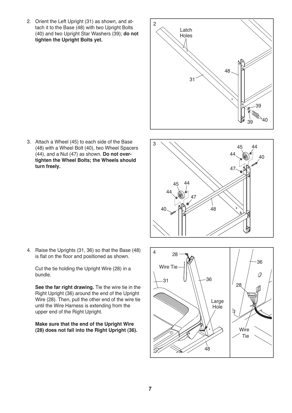
3. Attach a Wheel (45) to each side of the Base
(48) with a Wheel Bolt (40), two Wheel Spacers
(44), and a Nut (47) as shown. Do not over-
tighten the Wheel Bolts; the Wheels should
turn freely.
48
45
47
44
44
40
45
44
44
40
47
3
2
. Orient the Left Upright (31) as shown, and at-
tach it to the Base (48) with two Upright Bolts
(40) and two Upright Star Washers (39); do not
tighten the Upright Bolts yet.
48
31
39
39
40
Latch
Holes
2
4. Raise the Uprights (31, 36) so that the Base (48)
is flat on the floor and positioned as shown.
Cut the tie holding the Upright Wire (28) in a
bundle.
See the far right drawing. Tie the wire tie in the
Right Upright (36) around the end of the Upright
Wire (28). Then, pull the other end of the wire tie
until the Wire Harness is extending from the
upper end of the Right Upright.
Make sure that the end of the Upright Wire
(28) does not fall into the Right Upright (36).
4
28
Wire Tie
48
28
36
31
Large
Hole
Wire
Tie
36
 Loading...