9
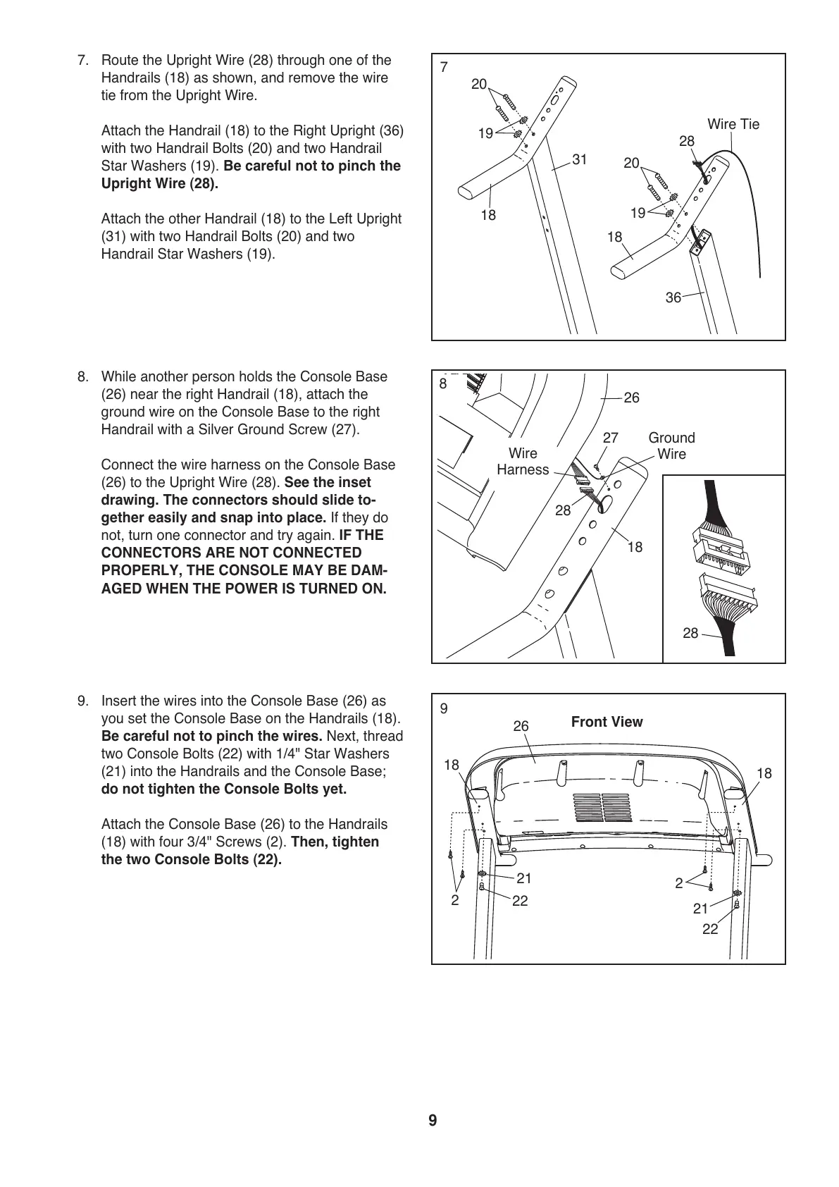
7. Route the Upright Wire (28) through one of the
Handrails (18) as shown, and remove the wire
tie from the Upright Wire.
Attach the Handrail (18) to the Right Upright (36)
w
ith two Handrail Bolts (20) and two Handrail
Star Washers (19). Be careful not to pinch the
Upright Wire (28).
Attach the other Handrail (18) to the Left Upright
(31) with two Handrail Bolts (20) and two
Handrail Star Washers (19).
31
28
W
ire Tie
20
19
1
8
20
19
18
7
28
18
8. While another person holds the Console Base
(26) near the right Handrail (18), attach the
ground wire on the Console Base to the right
Handrail with a Silver Ground Screw (27).
Connect the wire harness on the Console Base
(26) to the Upright Wire (28). See the inset
drawing. The connectors should slide to-
gether easily and snap into place. If they do
not, turn one connector and try again. IF THE
CONNECTORS ARE NOT CONNECTED
PROPERLY, THE CONSOLE MAY BE DAM-
AGED WHEN THE POWER IS TURNED ON.
27
26
Ground
Wire
28
Wire
Harness
8
22
9. Insert the wires into the Console Base (26) as
you set the Console Base on the Handrails (18).
Be careful not to pinch the wires. Next, thread
two Console Bolts (22) with 1/4" Star Washers
(21) into the Handrails and the Console Base;
do not tighten the Console Bolts yet.
Attach the Console Base (26) to the Handrails
(18) with four 3/4" Screws (2). Then, tighten
the two Console Bolts (22).
2
22
21
21
2
18
18
9
26
Front View
36
 Loading...