21
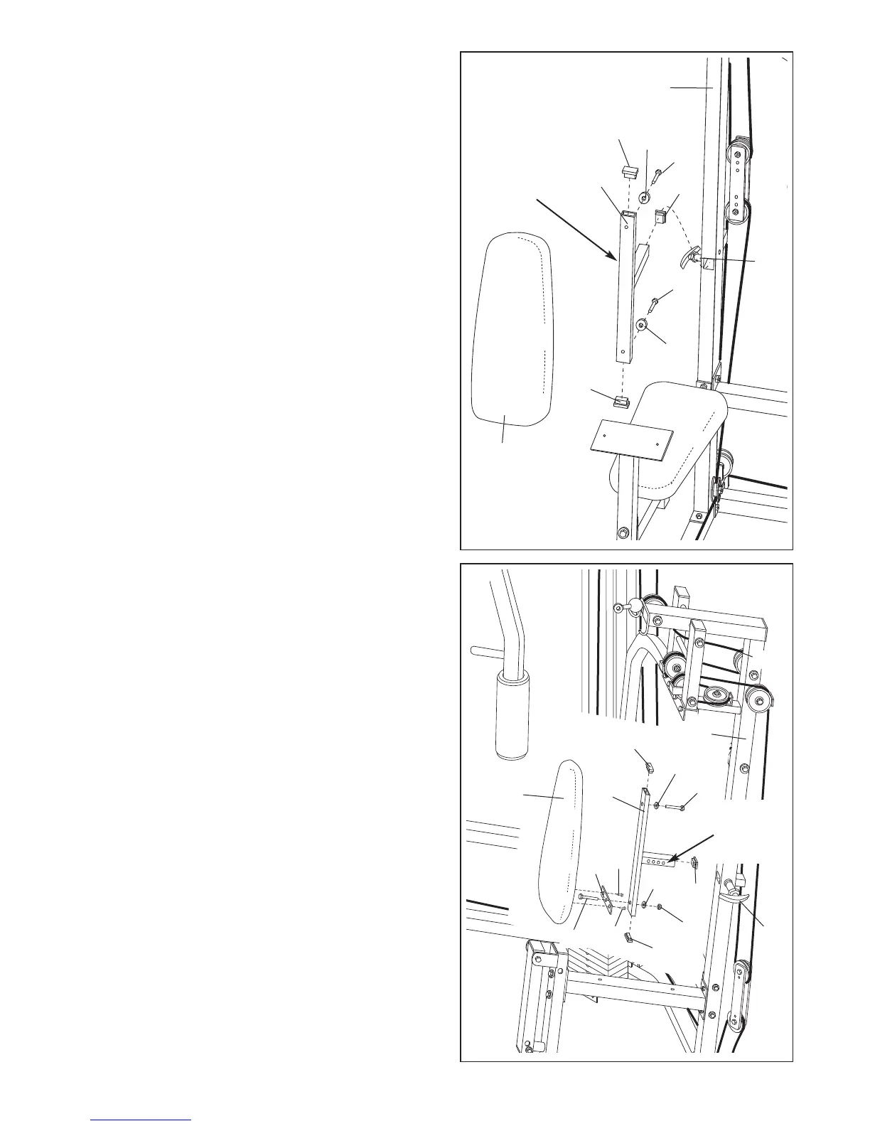
51. Press two 1” x 2” Inner Caps (83) and a 1 1/4” Square
Inner Cap (82) into the other Backrest Adjustment
Frame (70). Orient the Backrest Adjustment Frame so
the holes in the horizontal tube are on the side
shown.
Insert a 1/4” x 1 1/2” Carriage Bolt (101) into the cen-
ter hole in a Seat Plate (65). Attach the Seat Plate to
the Press Backrest (99) with two 1/4” x 3/4” Bolts
(49).
Insert the end of the 1/4” x 1 1/2” Carriage Bolt (101)
into the indicated hole in the Backrest Adjustment
Frame (70) and secure it with a 1/4” Flat Washer (71)
and a 1/4” Nylon Locknut (68). Secure the other end
of the Backrest with a 1/4” x 1 1/2” Screw (103) and a
1/4” Flat Washer (71).
Insert the tube on the Backrest Adjustment Frame
(70) into the indicated slot in the Press Upright (2)
and secure it with the Adjustment Handle (85).
51
103
2
78
71
68
85
82
71
83
83
49
49
70
101
65
99
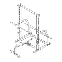
50. Press two 1” x 2” Inner Caps (83) and a 1 1/4” Square
Inner Cap (82) into a Backrest Adjustment Frame
(70). Orient the Backrest Adjustment Frame so the
h
oles in the horizontal tube are on the side shown.
I
dentify the Butterfly Backrest (12). It has only two
holes in the back. Attach the Butterfly Backrest to the
Backrest Adjustment Frame (70) with two 1/4” x 1 1/2”
Screws (103) and two 1/4” Flat Washers (71).
Insert the tube on the Backrest Adjustment Frame
(70) into the indicated slot in the Butterfly Upright (1)
and secure it with the Adjustment Handle (85).
50
83
71
103
83
103
8
2
71
85
12
70
1
H
oles in
Horizontal
Tube
Holes in
Horizontal
Tube