Chapter 4
P12×1-SP Installation, Configuration, and Operation
130
Copyright © 2004-2007, 2008, 2010, Harris Corporation
GVG
TEN-XL™
Control of
Harris
Routers:
GVG TEN-XL
NOTE: This submodule can also be set up to operate in LSERIAL mode. See
page 42 for more information about LSERIAL mode.
Use the GVG TEN-XL
1
configuration in conjunction with a Harris routing switcher
to allow control of the switcher via automation system software written for GVG
TEN-XL equipment. In this application, the P12×1-SP translates from Grass Valley
protocol to the protocol required by the Harris routing switcher.
GVG TEN-XL requires an address in order to perform switches. Since the GVG
TEN-XL SPT is designed for the Panacea Lite routing switcher series, the address
must reflect the Panel ID scheme used in the Panacea Lite routing switcher. The
address must be synchronized between the GVG TEN-XL controller and the
Panacea Lite routing switcher. The SPT merely decodes incoming addresses. Valid
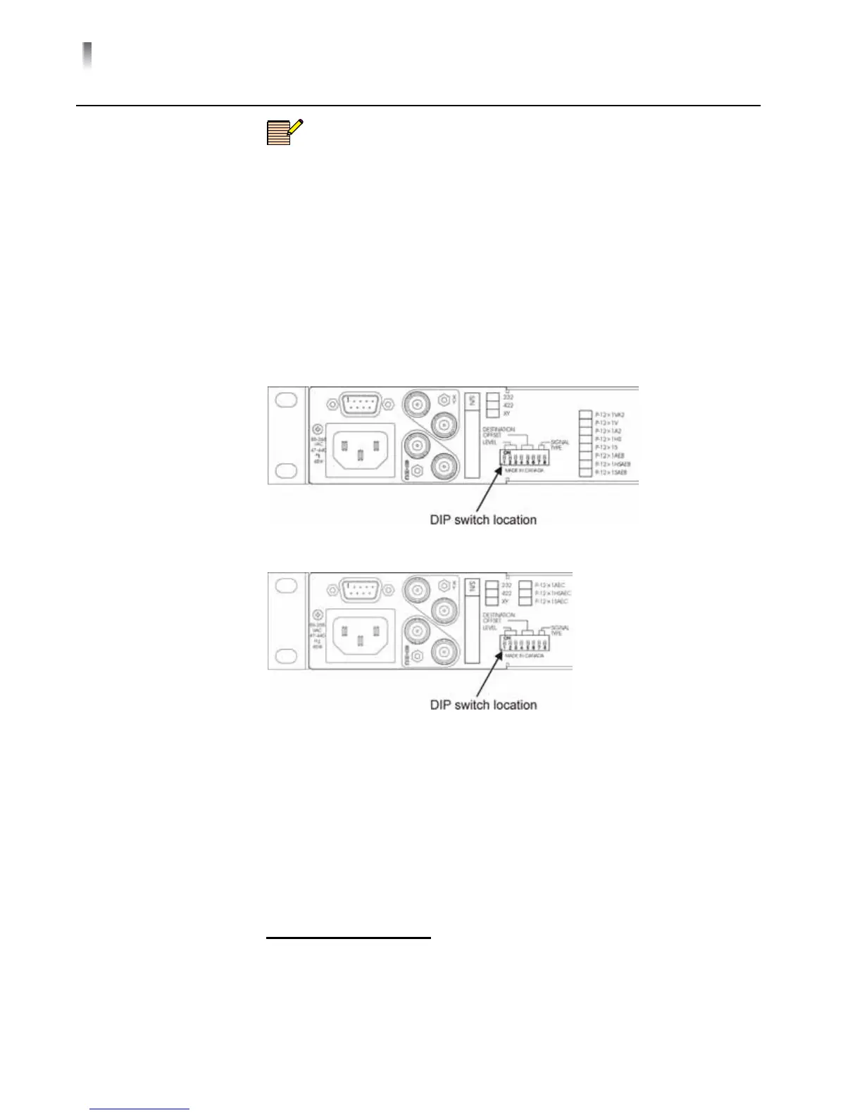
addresses are 6 bits in length. Figure 4-69 and Figure 4-70 show the location of
the DIP switch on the Panacea Lite back panel.
Figure 4-69 DIP Switch Location (-A2, -V, -VA2, -S, -SAEB, -HS, -HSAEB)
Figure 4-70 DIP Switch Location (-HSAEC, -SAEC)
Figure 4-75 on page 137 shows the DIP switch settings for the GVG TEN-XL
submodule. Figure 4-71 shows an example of the panel ID DIP switch settings on
the Panacea Lite router. You will need to set the DIP switches on both the
submodule and the router for this SPT to operate properly.
Figure 4-71 shows an example of the DIP switch settings for a panel ID that
represents the following elements: Video Level = 4; Audio Level = 5; and
Destination Offset = 8.
1
The GVG TEN-XL routing switcher, and corresponding router interface and automation sys-
tem software, are products of Grass Valley Group, a subsidiary of Thomson Broadcast Sys-
tems.
 Loading...